PDF Publication Title:
Text from PDF Page: 005
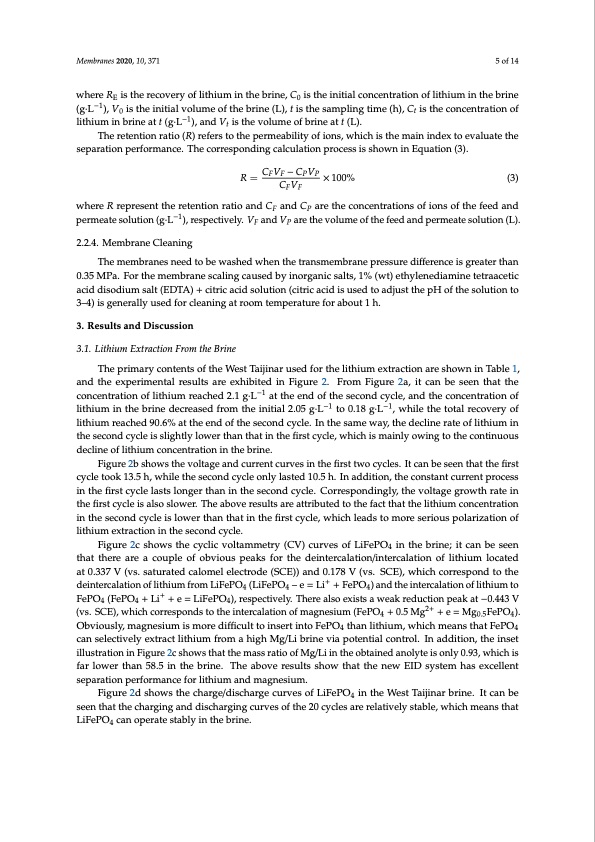
Membranes 2020, 10, 371 5 of 14 where RE is the recovery of lithium in the brine, C0 is the initial concentration of lithium in the brine (g·L−1), V0 is the initial volume of the brine (L), t is the sampling time (h), Ct is the concentration of lithium in brine at t (g·L−1), and Vt is the volume of brine at t (L). The retention ratio (R) refers to the permeability of ions, which is the main index to evaluate the separation performance. The corresponding calculation process is shown in Equation (3). R = CFVF − CPVP × 100% (3) CF VF where R represent the retention ratio and CF and CP are the concentrations of ions of the feed and permeate solution (g·L−1), respectively. VF and VP are the volume of the feed and permeate solution (L). 2.2.4. Membrane Cleaning The membranes need to be washed when the transmembrane pressure difference is greater than 0.35 MPa. For the membrane scaling caused by inorganic salts, 1% (wt) ethylenediamine tetraacetic acid disodium salt (EDTA) + citric acid solution (citric acid is used to adjust the pH of the solution to 3–4) is generally used for cleaning at room temperature for about 1 h. 3. Results and Discussion 3.1. Lithium Extraction From the Brine The primary contents of the West Taijinar used for the lithium extraction are shown in Table 1, and the experimental results are exhibited in Figure 2. From Figure 2a, it can be seen that the concentration of lithium reached 2.1 g·L−1 at the end of the second cycle, and the concentration of lithium in the brine decreased from the initial 2.05 g·L−1 to 0.18 g·L−1, while the total recovery of lithium reached 90.6% at the end of the second cycle. In the same way, the decline rate of lithium in the second cycle is slightly lower than that in the first cycle, which is mainly owing to the continuous decline of lithium concentration in the brine. Figure 2b shows the voltage and current curves in the first two cycles. It can be seen that the first cycle took 13.5 h, while the second cycle only lasted 10.5 h. In addition, the constant current process in the first cycle lasts longer than in the second cycle. Correspondingly, the voltage growth rate in the first cycle is also slower. The above results are attributed to the fact that the lithium concentration in the second cycle is lower than that in the first cycle, which leads to more serious polarization of lithium extraction in the second cycle. Figure 2c shows the cyclic voltammetry (CV) curves of LiFePO4 in the brine; it can be seen that there are a couple of obvious peaks for the deintercalation/intercalation of lithium located at 0.337 V (vs. saturated calomel electrode (SCE)) and 0.178 V (vs. SCE), which correspond to the deintercalation of lithium from LiFePO4 (LiFePO4 – e = Li+ + FePO4) and the intercalation of lithium to FePO4 (FePO4 + Li+ + e = LiFePO4), respectively. There also exists a weak reduction peak at −0.443 V (vs. SCE), which corresponds to the intercalation of magnesium (FePO4 + 0.5 Mg2+ + e = Mg0.5FePO4). Obviously, magnesium is more difficult to insert into FePO4 than lithium, which means that FePO4 can selectively extract lithium from a high Mg/Li brine via potential control. In addition, the inset illustration in Figure 2c shows that the mass ratio of Mg/Li in the obtained anolyte is only 0.93, which is far lower than 58.5 in the brine. The above results show that the new EID system has excellent separation performance for lithium and magnesium. Figure 2d shows the charge/discharge curves of LiFePO4 in the West Taijinar brine. It can be seen that the charging and discharging curves of the 20 cycles are relatively stable, which means that LiFePO4 can operate stably in the brine.PDF Image | Membrane Process for Preparing Lithium Carbonate
PDF Search Title:
Membrane Process for Preparing Lithium CarbonateOriginal File Name Searched:
membranes-10-00371.pdfDIY PDF Search: Google It | Yahoo | Bing
Product and Development Focus for Infinity Turbine
ORC Waste Heat Turbine and ORC System Build Plans: All turbine plans are $10,000 each. This allows you to build a system and then consider licensing for production after you have completed and tested a unit.Redox Flow Battery Technology: With the advent of the new USA tax credits for producing and selling batteries ($35/kW) we are focussing on a simple flow battery using shipping containers as the modular electrolyte storage units with tax credits up to $140,000 per system. Our main focus is on the salt battery. This battery can be used for both thermal and electrical storage applications. We call it the Cogeneration Battery or Cogen Battery. One project is converting salt (brine) based water conditioners to simultaneously produce power. In addition, there are many opportunities to extract Lithium from brine (salt lakes, groundwater, and producer water).Salt water or brine are huge sources for lithium. Most of the worlds lithium is acquired from a brine source. It's even in seawater in a low concentration. Brine is also a byproduct of huge powerplants, which can now use that as an electrolyte and a huge flow battery (which allows storage at the source).We welcome any business and equipment inquiries, as well as licensing our turbines for manufacturing.| CONTACT TEL: 608-238-6001 Email: greg@infinityturbine.com | RSS | AMP |