PDF Publication Title:
Text from PDF Page: 008
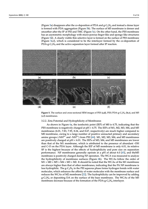
(d) Separations 2022, 9, 180 (e) (f) Figure 4. In situ high resolution C1s spectra (a–c) and N1s spectra (d–f) of the M5 membrane.8 of 16 The surface and cross-sectional SEM images of the PES, PES/PDA-g-C3N4 interlayer, and M5 membranes are shown in Figure 5. The porous surface of PES UF membrane (Fig- (Figure5a)disappearsaftertheco-depositionofPDAandg-CN andinsteadadenselayer ure5a)disappearsaftertheco-depositionofPDAandg-C3N34 an4dinsteadadenselayeris is formed with PDA aggregation (Figure 5b). The surface of M5 membrane is denser and formed with PDA aggregation (Figure 5b). The surface of M5 membrane is denser and smoother after the IP of PEI and TMC (Figure 5c). On the other hand, the PES membrane smoother after the IP of PEI and TMC (Figure 5c). On the other hand, the PES membrane has an asymmetric morphology with micro-porous finger-like and spongy-like structures has an asymmetric morphology with micro-porous finger-like and spongy-like structures (Figure 5d). A clearly visible thin selective layer is formed on the surface of PES membrane (Figure 5d). A clearly visible thin selective layer is formed on the surface of PES membrane (Figure 5e,f), which is considered to be the interlayer formed by the co-deposition of (Figure 5e, f), which is considered to be the interlayer formed by the co-deposition of PDA- PDA-g-C3N4 and the active separation layer formed after IP reaction. g-C3N4 and the active separation layer formed after IP reaction. (a) (b) (c) (d) (e) (f) Figure 5. The surface and cross-sectional SEM images of PES (a,d), PES/PDA-g-C3N4 (b,e), and M5 Figure 5. The surface and cross-sectional SEM images of PES (a,d), PES/PDA-g-C3N4 (b,e), and M5 (c,f) membranes. (c,f) membranes. 3.2.2. Zeta Potential and Hydrophilicity of Membranes As shown in Figure 6a, the isoelectric point (IEP) of M0 is 4.75, indicating that the PES membrane is negatively charged at pH > 4.75. The IEPs of M1, M2, M3, M4, and M5 membranes (6.01, 7.83, 7.95, 8.24, and 8.67, respectively) are much higher compared to M0 membrane, owing to a large number of positive unreacted primary and secondary amine groups (-NH3+ and -NH2+) from PEI [44]. M1, M2, M3, M4, and M5 membranes are positively charged at pH < 6.01. The IEPs of M3, M4, and M5 membranes are lower than that of the M1 membrane, which is attributed to the presence of abundant -OH and C-O on the PDA layer. Although the IEP of M5 membrane is only 6.01, its relative SF is the highest because of the effects of hydrophilicity and pore size on separation performance. NF membranes generally operate at a pH of about 6.0 [45], and theM5 membrane is positively charged during NF operation. The WCA was measured to analyze the hydrophilicity of membrane surfaces (Figure 6b). The WCAs follow the order of M1>M0>M5>M4>M3>M2. ItshouldbenotedthattheWCAsoftheM1membrane are always higher than that of other membranes, indicating that the PA NF membrane is less hydrophilic. The g-C3N4 in the PEI aqueous phase forms hydrogen bonds with water molecules, which enhances the affinity of water molecules with the membrane surface and reduces the WCAs of M2 membrane [22]. The hydrophilicity can be improved by adding g-C3N4 or depositing DA on the surface of the base membrane. The WCAs of the M5 membrane decrease because of the formation of the PDA-g-C3N4 interlayer.PDF Image | Nanofiltration Membrane Using Polydopamine Carbon Nitride
PDF Search Title:
Nanofiltration Membrane Using Polydopamine Carbon NitrideOriginal File Name Searched:
separations-09-00180.pdfDIY PDF Search: Google It | Yahoo | Bing
Product and Development Focus for Infinity Turbine
ORC Waste Heat Turbine and ORC System Build Plans: All turbine plans are $10,000 each. This allows you to build a system and then consider licensing for production after you have completed and tested a unit.Redox Flow Battery Technology: With the advent of the new USA tax credits for producing and selling batteries ($35/kW) we are focussing on a simple flow battery using shipping containers as the modular electrolyte storage units with tax credits up to $140,000 per system. Our main focus is on the salt battery. This battery can be used for both thermal and electrical storage applications. We call it the Cogeneration Battery or Cogen Battery. One project is converting salt (brine) based water conditioners to simultaneously produce power. In addition, there are many opportunities to extract Lithium from brine (salt lakes, groundwater, and producer water).Salt water or brine are huge sources for lithium. Most of the worlds lithium is acquired from a brine source. It's even in seawater in a low concentration. Brine is also a byproduct of huge powerplants, which can now use that as an electrolyte and a huge flow battery (which allows storage at the source).We welcome any business and equipment inquiries, as well as licensing our turbines for manufacturing.| CONTACT TEL: 608-238-6001 Email: greg@infinityturbine.com | RSS | AMP |