PDF Publication Title:
Text from PDF Page: 012
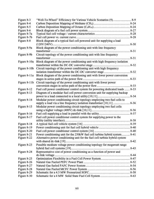
Figure 8-3 Figure 8-4 Figure 8-5 Figure 8-6 Figure 8-7a Figure 8-7b Figure 8-8 Figure 8-9a Figure 8-9b Figure 8-10a Figure 8-10b Figure 8-11a Figure 8-11b Figure 8-12 Figure 8-13 Figure 8-14 Figure 8-15 Figure 8-16 Figure 8-17 Figure 8-18 Figure 8-19 Figure 8-20 Figure 8-21 Figure 8-22 Figure 8-23 Figure 8-24 Figure 8-25 Figure 8-26 Figure 8-27 Figure 8-28 Figure 8-29 Figure 8-30 “Well-To-Wheel” Efficiency for Various Vehicle Scenarios (9) ........................ 8-9 Carbon Deposition Mapping of Methane (CH4) ................................................ 8-24 Carbon Deposition Mapping of Octane (C8H18)................................................ 8-24 Block diagram of a fuel cell power system........................................................ 8-27 Typical fuel cell voltage / current characteristics .............................................. 8-28 Fuel cell power vs. current curve ....................................................................... 8-28 Block diagram of a typical fuel cell powered unit for supplying a load (120V/240V) ...................................................................................................... 8-30 Block diagram of the power conditioning unit with line frequency transformer ......................................................................................................... 8-31 Circuit topology of the power conditioning unit with line frequency transformer ......................................................................................................... 8-31 Block diagram of the power conditioning unit with high frequency isolation transformer within the DC-DC converter stage ................................................. 8-32 Circuit topology of the power conditioning unit with high frequency isolation transformer within the DC-DC converter stage .................................. 8-32 Block diagram of the power conditioning unit with fewer power conversion stages in series path of the power flow .............................................................. 8-33 Circuit topology of the power conditioning unit with fewer power conversion stages in series path of the power flow............................................ 8-33 Fuel cell power conditioner control system for powering dedicated loads ....... 8-33 Diagram of a modular fuel cell power conversion unit for supplying backup power to a load connected to a local utility [10,11]........................................... 8-34 Modular power conditioning circuit topology employing two fuel cells to supply a load via a line frequency isolation transformer [10,11] ...................... 8-36 Modular power conditioning circuit topology employing two fuel cells using a higher voltage (400V) dc-link [10,11]................................................... 8-36 Fuel cell supplying a load in parallel with the utility......................................... 8-37 Fuel cell power conditioner control system for supplying power to the utility (utility interface)...................................................................................... 8-38 A typical fuel cell vehicle system [16] .............................................................. 8-39 Power conditioning unit for fuel cell hybrid vehicle ......................................... 8-40 Fuel cell power conditioner control system [16] ............................................... 8-40 Power conditioning unit for the 250kW fuel cell turbine hybrid system........... 8-41 Alternative power conditioning unit for the fuel cell turbine hybrid system with shared dc-link [19] ..................................................................................... 8-42 Possible medium voltage power conditioning topology for megawatt range hybrid fuel cell systems [19].............................................................................. 8-43 Representative cost of power conditioning as a function of power and dc-link voltage ................................................................................................... 8-44 Optimization Flexibility in a Fuel Cell Power System ...................................... 8-47 Natural Gas Fueled PEFC Power Plant ............................................................. 8-52 Natural Gas fueled PAFC Power System .......................................................... 8-54 Natural Gas Fueled MCFC Power System ........................................................ 8-56 Schematic for a 4.5 MW Pressurized SOFC...................................................... 8-58 Schematic for a 4 MW Solid State Fuel Cell System ....................................... 8-63 xiiPDF Image | Fuel Cell Handbook (Seventh Edition)

PDF Search Title:
Fuel Cell Handbook (Seventh Edition)Original File Name Searched:
fuel-cell-handbook.pdfDIY PDF Search: Google It | Yahoo | Bing
NFT (Non Fungible Token): Buy our tech, design, development or system NFT and become part of our tech NFT network... More Info
IT XR Project Redstone NFT Available for Sale: NFT for high tech turbine design with one part 3D printed counter-rotating energy turbine. Be part of the future with this NFT. Can be bought and sold but only one design NFT exists. Royalties go to the developer (Infinity) to keep enhancing design and applications... More Info
Infinity Turbine IT XR Project Redstone Design: NFT for sale... NFT for high tech turbine design with one part 3D printed counter-rotating energy turbine. Includes all rights to this turbine design, including license for Fluid Handling Block I and II for the turbine assembly and housing. The NFT includes the blueprints (cad/cam), revenue streams, and all future development of the IT XR Project Redstone... More Info
Infinity Turbine ROT Radial Outflow Turbine 24 Design and Worldwide Rights: NFT for sale... NFT for the ROT 24 energy turbine. Be part of the future with this NFT. This design can be bought and sold but only one design NFT exists. You may manufacture the unit, or get the revenues from its sale from Infinity Turbine. Royalties go to the developer (Infinity) to keep enhancing design and applications... More Info
Infinity Supercritical CO2 10 Liter Extractor Design and Worldwide Rights: The Infinity Supercritical 10L CO2 extractor is for botanical oil extraction, which is rich in terpenes and can produce shelf ready full spectrum oil. With over 5 years of development, this industry leader mature extractor machine has been sold since 2015 and is part of many profitable businesses. The process can also be used for electrowinning, e-waste recycling, and lithium battery recycling, gold mining electronic wastes, precious metals. CO2 can also be used in a reverse fuel cell with nafion to make a gas-to-liquids fuel, such as methanol, ethanol and butanol or ethylene. Supercritical CO2 has also been used for treating nafion to make it more effective catalyst. This NFT is for the purchase of worldwide rights which includes the design. More Info
NFT (Non Fungible Token): Buy our tech, design, development or system NFT and become part of our tech NFT network... More Info
Infinity Turbine Products: Special for this month, any plans are $10,000 for complete Cad/Cam blueprints. License is for one build. Try before you buy a production license. May pay by Bitcoin or other Crypto. Products Page... More Info
| CONTACT TEL: 608-238-6001 Email: greg@infinityturbine.com | RSS | AMP |