PDF Publication Title:
Text from PDF Page: 016
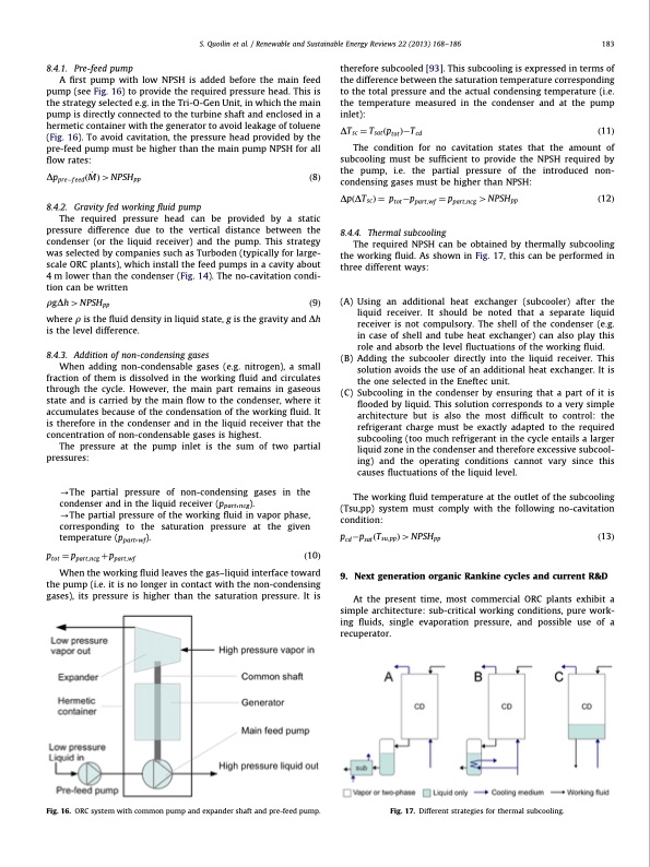
8.4.1. Pre-feed pump A first pump with low NPSH is added before the main feed pump (see Fig. 16) to provide the required pressure head. This is the strategy selected e.g. in the Tri-O-Gen Unit, in which the main pump is directly connected to the turbine shaft and enclosed in a hermetic container with the generator to avoid leakage of toluene (Fig. 16). To avoid cavitation, the pressure head provided by the pre-feed pump must be higher than the main pump NPSH for all flow rates: DpprefeedðM_ Þ4NPSHpp ð8Þ 8.4.2. Gravity fed working fluid pump The required pressure head can be provided by a static pressure difference due to the vertical distance between the condenser (or the liquid receiver) and the pump. This strategy was selected by companies such as Turboden (typically for large- scale ORC plants), which install the feed pumps in a cavity about 4 m lower than the condenser (Fig. 14). The no-cavitation condi- tion can be written rgDh 4 NPSHpp ð9Þ where r is the fluid density in liquid state, g is the gravity and Dh is the level difference. 8.4.3. Addition of non-condensing gases When adding non-condensable gases (e.g. nitrogen), a small fraction of them is dissolved in the working fluid and circulates through the cycle. However, the main part remains in gaseous state and is carried by the main flow to the condenser, where it accumulates because of the condensation of the working fluid. It is therefore in the condenser and in the liquid receiver that the concentration of non-condensable gases is highest. The pressure at the pump inlet is the sum of two partial pressures: -The partial pressure of non-condensing gases in the condenser and in the liquid receiver (ppart,ncg). -The partial pressure of the working fluid in vapor phase, corresponding to the saturation pressure at the given temperature (ppart,wf). ptot 1⁄4 ppart,ncg þ ppart,wf ð10Þ When the working fluid leaves the gas–liquid interface toward the pump (i.e. it is no longer in contact with the non-condensing gases), its pressure is higher than the saturation pressure. It is therefore subcooled [93]. This subcooling is expressed in terms of the difference between the saturation temperature corresponding to the total pressure and the actual condensing temperature (i.e. the temperature measured in the condenser and at the pump inlet): DTsc 1⁄4 TsatðptotÞTcd ð11Þ The condition for no cavitation states that the amount of subcooling must be sufficient to provide the NPSH required by the pump, i.e. the partial pressure of the introduced non- condensing gases must be higher than NPSH: DpðDTscÞ 1⁄4 ptotppart,wf 1⁄4 ppart,ncg 4NPSHpp ð12Þ 8.4.4. Thermal subcooling The required NPSH can be obtained by thermally subcooling the working fluid. As shown in Fig. 17, this can be performed in three different ways: (A) Using an additional heat exchanger (subcooler) after the liquid receiver. It should be noted that a separate liquid receiver is not compulsory. The shell of the condenser (e.g. in case of shell and tube heat exchanger) can also play this role and absorb the level fluctuations of the working fluid. (B) Adding the subcooler directly into the liquid receiver. This solution avoids the use of an additional heat exchanger. It is the one selected in the Eneftec unit. (C) Subcooling in the condenser by ensuring that a part of it is flooded by liquid. This solution corresponds to a very simple architecture but is also the most difficult to control: the refrigerant charge must be exactly adapted to the required subcooling (too much refrigerant in the cycle entails a larger liquid zone in the condenser and therefore excessive subcool- ing) and the operating conditions cannot vary since this causes fluctuations of the liquid level. The working fluid temperature at the outlet of the subcooling (Tsu,pp) system must comply with the following no-cavitation condition: pcdpsatðTsu,ppÞ4NPSHpp ð13Þ 9. Next generation organic Rankine cycles and current R&D At the present time, most commercial ORC plants exhibit a simple architecture: sub-critical working conditions, pure work- ing fluids, single evaporation pressure, and possible use of a recuperator. S. Quoilin et al. / Renewable and Sustainable Energy Reviews 22 (2013) 168–186 183 Fig. 16. ORC system with common pump and expander shaft and pre-feed pump. Fig. 17. Different strategies for thermal subcooling.PDF Image | Techno-economic survey of Organic Rankine Cycle (ORC) systems
PDF Search Title:
Techno-economic survey of Organic Rankine Cycle (ORC) systemsOriginal File Name Searched:
1_s2.0_S1364032113000592_main.pdfDIY PDF Search: Google It | Yahoo | Bing
NFT (Non Fungible Token): Buy our tech, design, development or system NFT and become part of our tech NFT network... More Info
IT XR Project Redstone NFT Available for Sale: NFT for high tech turbine design with one part 3D printed counter-rotating energy turbine. Be part of the future with this NFT. Can be bought and sold but only one design NFT exists. Royalties go to the developer (Infinity) to keep enhancing design and applications... More Info
Infinity Turbine IT XR Project Redstone Design: NFT for sale... NFT for high tech turbine design with one part 3D printed counter-rotating energy turbine. Includes all rights to this turbine design, including license for Fluid Handling Block I and II for the turbine assembly and housing. The NFT includes the blueprints (cad/cam), revenue streams, and all future development of the IT XR Project Redstone... More Info
Infinity Turbine ROT Radial Outflow Turbine 24 Design and Worldwide Rights: NFT for sale... NFT for the ROT 24 energy turbine. Be part of the future with this NFT. This design can be bought and sold but only one design NFT exists. You may manufacture the unit, or get the revenues from its sale from Infinity Turbine. Royalties go to the developer (Infinity) to keep enhancing design and applications... More Info
Infinity Supercritical CO2 10 Liter Extractor Design and Worldwide Rights: The Infinity Supercritical 10L CO2 extractor is for botanical oil extraction, which is rich in terpenes and can produce shelf ready full spectrum oil. With over 5 years of development, this industry leader mature extractor machine has been sold since 2015 and is part of many profitable businesses. The process can also be used for electrowinning, e-waste recycling, and lithium battery recycling, gold mining electronic wastes, precious metals. CO2 can also be used in a reverse fuel cell with nafion to make a gas-to-liquids fuel, such as methanol, ethanol and butanol or ethylene. Supercritical CO2 has also been used for treating nafion to make it more effective catalyst. This NFT is for the purchase of worldwide rights which includes the design. More Info
NFT (Non Fungible Token): Buy our tech, design, development or system NFT and become part of our tech NFT network... More Info
Infinity Turbine Products: Special for this month, any plans are $10,000 for complete Cad/Cam blueprints. License is for one build. Try before you buy a production license. May pay by Bitcoin or other Crypto. Products Page... More Info
| CONTACT TEL: 608-238-6001 Email: greg@infinityturbine.com | RSS | AMP |