PDF Publication Title:
Text from PDF Page: 112
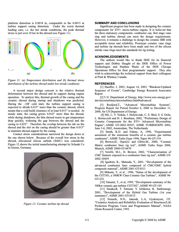
platform distortion is 0.0018 in, comparable to the 0.0015 in turbine support casing distortion. Under the worst thermal loading case, i.e. the hot streak conditions, the peak thermal stress is just over 10 ksi in the shroud (see Figure 11). SUMMARY AND CONCLUSIONS Significant progress has been made in designing the ceramic components for ST5+ micro-turbine engine. It is believed that the three stationery components- combustor can, first stage vane ring and turbine shroud can meet the design requirements. However, it remains a challenge to design the ceramic IBR with acceptable stress and reliability. Prototype ceramic vane rings and turbine tip shrouds have been made and two of the silicon nitride vane rings meet the standards for rig testing. ACKNOWLEDGEMENTS The authors would like to thank DOE for its financial support and Debbie Haught of the DOE Office of Power Technologies and Stephen Waslo of the DOE Chicago Operations Office for their programmatic support. They also wish to acknowledge the technical support from their colleagues at Pratt & Whitney Canada. REFERENCES [1] Stauffer, J, 2003, August 14, 2003, “Blackout:Updated Sequence of Events”, Cambridge Energy Research Associates Report [2] U.S. Department of Energy, http://www.eere.energy.gov/ der/microturbines/microturbines.html#advanced [3] Rosfjord,T., “Advanced Microturbine Systems”, Progress Report for Period October 6, 2000 to December 31, 2000, for US Department of Energy. [4] Shi, J., V. Vedula, J. Holowczak, C. E. Bird, S. S. Ochs, L. Bertuccioli and D. J. Bombara, 2002, “Preliminary Design of Ceramic Components for the ST5+ Advanced Microturbine Engine”, ASME GT-2002-30547, ASME TURBOEXPO 2002, June 3-6, 2002, Amsterdam, The Netherlands [5] Smith, K.O. and Fahme, A, 1996, “Experimental assesment of the emissions benefits of a ceramic gas turbine combustor”, ASME Turbo Expo 1996, Paper 96-GT-318 [6] Brewer,D., Ojard,G. and Gibler,M., 2000, “Ceramic Matrix combustor liner rig test”, ASME Turbo Expo 2000, Munich, ASME 2000-GT-0670 [7] Verrilli, M.J., D. Brewer, 2002, “Characterisation of CMC fastners exposed in a combustor liner rig test”, ASME GT- 2002-30459 [8] Igashira, K., Matsuda, Y., 2001, “Development of the advanced combustor liner composed of CMC/GMC hybrid composite material”, ASME 2001-GT-0511 [9] Mikami, T., et al , 1996, “Status of the development of the CGT301, a 300KW Class Ceramic Gas Turbine”, ASME 96- GT-252. [10] Tatsumi, T., et al, 1999, “Development summary of the 300kw ceramic gas turbine CGT302”, ASME 99-GT-105 [11] Tanaka,R, T. Tatsumi, Y. Ichikawa, K. Sanbonsugi, 2001, “Development of the Hybrid Gas Turbine (1st year summary)”, ASME 2001-GT-0515 [12] Nemeth, N.N., Janosik, L.A, Gyekenyesi, J.P., "Ceramics Analysis and Reliability Evaluation of Structures/Life Prediction Program, Users and Programmers Manual", NASA Glenn Research Center, 1993. (a) (b) Figure 11: (a) Temperature distribution and (b) thermal stress distribution of the turbine shroud under hot streak conditions A second major design concern is the relative thermal deformation between the shroud and its support during engine operation. To analyze this, thermal growth of the casing and the ceramic shroud during startup and shutdown was predicted. During the –10F cold start, the turbine support casing is expected to shrink 0.015” more than the ceramic shroud, which means that a cold build clearance of at least 0.015” is needed. At steady state, the casing grows 0.010” more than the shroud, while during shutdown, the thin shroud reacts to gas temperature drop quickly, widening the gap between the shroud and the casing to 0.025”. Therefore the overlap between the tab on the shroud and the slot on the casing should be greater than 0.015” to maintain shroud support by the casing. Contact stress considerations narrowed the design down to the one shown below. Because of the overall low stress in the shroud, siliconized silicon carbide (SiSiC) was considered. Figure 12 shows the initial manufacturing attempt by Schunk Co in Gissen, Germany. Figure 12: Ceramic turbine tip shroud 111 Copyright © 2004 by ASMEPDF Image | ADVANCED MICROTURBINE SYSTEMS Final Report for Tasks 1 Through 4 and Task 6
PDF Search Title:
ADVANCED MICROTURBINE SYSTEMS Final Report for Tasks 1 Through 4 and Task 6Original File Name Searched:
AdvancedMicroturbineSystems_924484.pdfDIY PDF Search: Google It | Yahoo | Bing
NFT (Non Fungible Token): Buy our tech, design, development or system NFT and become part of our tech NFT network... More Info
IT XR Project Redstone NFT Available for Sale: NFT for high tech turbine design with one part 3D printed counter-rotating energy turbine. Be part of the future with this NFT. Can be bought and sold but only one design NFT exists. Royalties go to the developer (Infinity) to keep enhancing design and applications... More Info
Infinity Turbine IT XR Project Redstone Design: NFT for sale... NFT for high tech turbine design with one part 3D printed counter-rotating energy turbine. Includes all rights to this turbine design, including license for Fluid Handling Block I and II for the turbine assembly and housing. The NFT includes the blueprints (cad/cam), revenue streams, and all future development of the IT XR Project Redstone... More Info
Infinity Turbine ROT Radial Outflow Turbine 24 Design and Worldwide Rights: NFT for sale... NFT for the ROT 24 energy turbine. Be part of the future with this NFT. This design can be bought and sold but only one design NFT exists. You may manufacture the unit, or get the revenues from its sale from Infinity Turbine. Royalties go to the developer (Infinity) to keep enhancing design and applications... More Info
Infinity Supercritical CO2 10 Liter Extractor Design and Worldwide Rights: The Infinity Supercritical 10L CO2 extractor is for botanical oil extraction, which is rich in terpenes and can produce shelf ready full spectrum oil. With over 5 years of development, this industry leader mature extractor machine has been sold since 2015 and is part of many profitable businesses. The process can also be used for electrowinning, e-waste recycling, and lithium battery recycling, gold mining electronic wastes, precious metals. CO2 can also be used in a reverse fuel cell with nafion to make a gas-to-liquids fuel, such as methanol, ethanol and butanol or ethylene. Supercritical CO2 has also been used for treating nafion to make it more effective catalyst. This NFT is for the purchase of worldwide rights which includes the design. More Info
NFT (Non Fungible Token): Buy our tech, design, development or system NFT and become part of our tech NFT network... More Info
Infinity Turbine Products: Special for this month, any plans are $10,000 for complete Cad/Cam blueprints. License is for one build. Try before you buy a production license. May pay by Bitcoin or other Crypto. Products Page... More Info
| CONTACT TEL: 608-238-6001 Email: greg@infinityturbine.com | RSS | AMP |