PDF Publication Title:
Text from PDF Page: 045
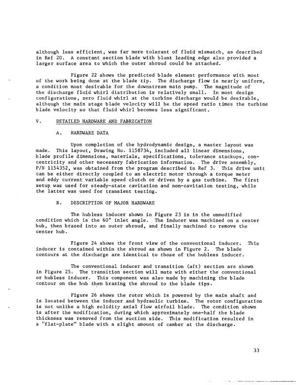
although less efficient, was far more tolerant of fluid mismatch, as described in Ref 20. A constant section blade with blunt leading edge also provided a larger surface area to which the outer shroud could be attached. Figure 22 shows the predicted blade element performance with most of the work being done at the blade tip. The discharge flow is nearly uniform, a condition most desirable for the downstream main pump. The magnitude of the discharge fluid whirl distribution is relatively small. In most design configurations, zero fluid whirl at the turbine discharge would be desirable, although the main stage blade velocity will be the speed ratio times the turbine blade velocity so that fluid whirl becomes less significant. V. DETAILED HARDWARE AND FABRICATION A. HARDWARE DATA Upon completion of the hydrodynamic design, a master layout was made. This layout, Drawing No. 1158734, included all linear dimensions, blade profile dimensions, materials, specifications, tolerance stackups, con- centricity and other necessary fabrication information. The drive assembly, P/N 1154352, was obtained from the program described in Ref 3. This drive unit can be either directly coupled to an electric motor through a torque meter and eddy current variable speed clutch or driven by a gas turbine. The first setup was used for steady-state cavitation and non-cavitation testing, while the latter was used for transient testing. B. DESCRIPTION OF MAJOR HARDWARE The hubless inducer shown in Figure 23 is in the unmodified condition which is the 60° inlet angle. The inducer was machined on a center hub, then brazed into an outer shroud, and finally machined to remove the center hub. Figure 24 shows the front view of the conventional inducer. This inducer is contained within the shroud as shown in Figure 2. The blade contours at the discharge are identical to those of the hubless inducer. The conventional inducer and transition (aft) section are shown in Figure 25. The transition section will mate with either the conventional or hubless inducer. This component was also made by machining the blade contour on the hub then brazing the shroud to the blade tips. Figure 26 shows the rotor which is powered by the main shaft and is located between the inducer and hydraulic turbine. The rotor configuration is not unlike a high solidity axial flow airfoil blade. The condition shown is after the modification, during which approximately one-half the blade thickness was removed from the suction side. This modification resulted in a "flat-plate" blade with a slight amount of camber at the discharge. 33PDF Image | HUBLESS INDUCER FLOW HYDRAULIC TURBINE INDUCER BOOST PUMP
PDF Search Title:
HUBLESS INDUCER FLOW HYDRAULIC TURBINE INDUCER BOOST PUMPOriginal File Name Searched:
Inducer_turbine_pump.pdfDIY PDF Search: Google It | Yahoo | Bing
NFT (Non Fungible Token): Buy our tech, design, development or system NFT and become part of our tech NFT network... More Info
IT XR Project Redstone NFT Available for Sale: NFT for high tech turbine design with one part 3D printed counter-rotating energy turbine. Be part of the future with this NFT. Can be bought and sold but only one design NFT exists. Royalties go to the developer (Infinity) to keep enhancing design and applications... More Info
Infinity Turbine IT XR Project Redstone Design: NFT for sale... NFT for high tech turbine design with one part 3D printed counter-rotating energy turbine. Includes all rights to this turbine design, including license for Fluid Handling Block I and II for the turbine assembly and housing. The NFT includes the blueprints (cad/cam), revenue streams, and all future development of the IT XR Project Redstone... More Info
Infinity Turbine ROT Radial Outflow Turbine 24 Design and Worldwide Rights: NFT for sale... NFT for the ROT 24 energy turbine. Be part of the future with this NFT. This design can be bought and sold but only one design NFT exists. You may manufacture the unit, or get the revenues from its sale from Infinity Turbine. Royalties go to the developer (Infinity) to keep enhancing design and applications... More Info
Infinity Supercritical CO2 10 Liter Extractor Design and Worldwide Rights: The Infinity Supercritical 10L CO2 extractor is for botanical oil extraction, which is rich in terpenes and can produce shelf ready full spectrum oil. With over 5 years of development, this industry leader mature extractor machine has been sold since 2015 and is part of many profitable businesses. The process can also be used for electrowinning, e-waste recycling, and lithium battery recycling, gold mining electronic wastes, precious metals. CO2 can also be used in a reverse fuel cell with nafion to make a gas-to-liquids fuel, such as methanol, ethanol and butanol or ethylene. Supercritical CO2 has also been used for treating nafion to make it more effective catalyst. This NFT is for the purchase of worldwide rights which includes the design. More Info
NFT (Non Fungible Token): Buy our tech, design, development or system NFT and become part of our tech NFT network... More Info
Infinity Turbine Products: Special for this month, any plans are $10,000 for complete Cad/Cam blueprints. License is for one build. Try before you buy a production license. May pay by Bitcoin or other Crypto. Products Page... More Info
| CONTACT TEL: 608-238-6001 Email: greg@infinityturbine.com | RSS | AMP |