PDF Publication Title:
Text from PDF Page: 014
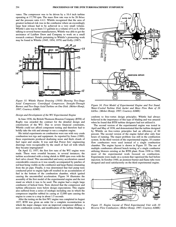
294 PROCEEDINGS OF THE 29TH TURBOMACHINERY SYMPOSIUM vanes. The compressor was to be driven by a 16.4 inch turbine operating at 17,750 rpm. The mass flow rate was to be 26 lb/sec and the pressure ratio 4.4:1. Whittle recognized that the area of greatest technical risk was in the combustor where an exceedingly large heat release had to be achieved in a very small volume. Whittle’s aim was to burn 3.3 gal/min in a volume of 6 cu ft. After talking to several burner manufacturers, Whittle was able to get the assistance of Laidlaw Drew and Company to work on a small research contract. Details pertaining to Whittle’s pioneering work may be found in Whittle (1945, 1954, 1979) and Golly (1987). Figure 33. Whittle Patent Drawing (1930) Showing Two-Stage Axial Compressor, Centrifugal Compressor, Straight-Through Burner, and Two-Stage Axial Turbine on One Disk. (Meher-Homji, 1997; Courtesy ASME) Design and Development of the WU Experimental Engine In June 1936, the British Thomson-Houston Company (BTH) of Rugby was awarded the contract for the detailed design and construction of the WU. Due to severe financial constraints, Whittle could not afford component testing and therefore had to boldly take the risk and attempt to run a complete engine. His initial experiments on combustion were run with very crude combustion test rigs and equipment. As reported by Jones (1989), these experiments produced deafening noise and thick clouds of fuel vapor and smoke. It was said that Power Jets’ engineering drawings were recognizable by the smell of fuel oil with which they became impregnated! On April 12, 1937, the first few runs of the WU engine were made. These were eventful because, in several instances, the turbine accelerated with a rising shriek to 8000 rpm even with the fuel valve closed. This uncontrolled and noisy acceleration caused considerable concern as it was usually accompanied by patches of red heat being visible on the combustor and large flames emanating from the jet pipe. Finally, it was determined that fuel pump tests conducted prior to engine light-off resulted in an accumulation of fuel in the bottom of the combustion chamber, which ignited causing the uncontrolled acceleration. Figure 34 illustrates the assembly of the first model of the experimental engine and the test stand on which it was to be used. The engine had a single large combustor of helical form. Tests showed that the compressor and turbine efficiencies were below design expectations. This engine also suffered from a series of mishaps including one in which the compressor impeller rubbed its casing at 12,000 rpm causing the engine to come to a stop in about 1.5 seconds. After the testing on the first WU engine was completed in August 1937, BTH was given an order for a complete reconstruction in which the major changes were an improved compressor diffuser, a new combustion system, and modification of the turbine blading to Figure 34. First Model of Experimental Engine and Test Stand, Water-Cooled Turbine Disk Jacket and Mass Flow Rate of 26 Lb/Sec. (Meher-Homji, 1997; Courtesy ASME) conform to free-vortex design principles. Whittle had always believed in the importance of this type of blading and was amazed when he found that BTH turbine designers had not utilized it. The second version of the experimental engine was tested in April and May of 1938, and demonstrated that the turbine designed by Whittle on free-vortex principles had an efficiency of 84 percent. The second version of the engine failed after only four hours of running. The major problem was still in the combustion system. In the third version of the experimental engine, 10 counter flow combustors were used instead of a single combustion chamber. The engine layout is shown in Figure 35. The use of multiple combustors allowed bench testing of a single combustor utilizing blowers existing at the BTH plant. From 1938 to 1940, most of the experimental work focused on combustion. Experiments were made on a system that vaporized the fuel before injection. In October 1940, an atomizer burner and flame tube were designed and used satisfactorily on the third experimental engine. Figure 35. Engine Layout of Third Experimental Unit with 10 Reverse Flow Combustors. (Meher-Homji, 1997; Courtesy ASME)PDF Image | THE HISTORICAL EVOLUTION OF TURBOMACHINERY
PDF Search Title:
THE HISTORICAL EVOLUTION OF TURBOMACHINERYOriginal File Name Searched:
t29pg281.pdfDIY PDF Search: Google It | Yahoo | Bing
NFT (Non Fungible Token): Buy our tech, design, development or system NFT and become part of our tech NFT network... More Info
IT XR Project Redstone NFT Available for Sale: NFT for high tech turbine design with one part 3D printed counter-rotating energy turbine. Be part of the future with this NFT. Can be bought and sold but only one design NFT exists. Royalties go to the developer (Infinity) to keep enhancing design and applications... More Info
Infinity Turbine IT XR Project Redstone Design: NFT for sale... NFT for high tech turbine design with one part 3D printed counter-rotating energy turbine. Includes all rights to this turbine design, including license for Fluid Handling Block I and II for the turbine assembly and housing. The NFT includes the blueprints (cad/cam), revenue streams, and all future development of the IT XR Project Redstone... More Info
Infinity Turbine ROT Radial Outflow Turbine 24 Design and Worldwide Rights: NFT for sale... NFT for the ROT 24 energy turbine. Be part of the future with this NFT. This design can be bought and sold but only one design NFT exists. You may manufacture the unit, or get the revenues from its sale from Infinity Turbine. Royalties go to the developer (Infinity) to keep enhancing design and applications... More Info
Infinity Supercritical CO2 10 Liter Extractor Design and Worldwide Rights: The Infinity Supercritical 10L CO2 extractor is for botanical oil extraction, which is rich in terpenes and can produce shelf ready full spectrum oil. With over 5 years of development, this industry leader mature extractor machine has been sold since 2015 and is part of many profitable businesses. The process can also be used for electrowinning, e-waste recycling, and lithium battery recycling, gold mining electronic wastes, precious metals. CO2 can also be used in a reverse fuel cell with nafion to make a gas-to-liquids fuel, such as methanol, ethanol and butanol or ethylene. Supercritical CO2 has also been used for treating nafion to make it more effective catalyst. This NFT is for the purchase of worldwide rights which includes the design. More Info
NFT (Non Fungible Token): Buy our tech, design, development or system NFT and become part of our tech NFT network... More Info
Infinity Turbine Products: Special for this month, any plans are $10,000 for complete Cad/Cam blueprints. License is for one build. Try before you buy a production license. May pay by Bitcoin or other Crypto. Products Page... More Info
| CONTACT TEL: 608-238-6001 Email: greg@infinityturbine.com | RSS | AMP |