PDF Publication Title:
Text from PDF Page: 008
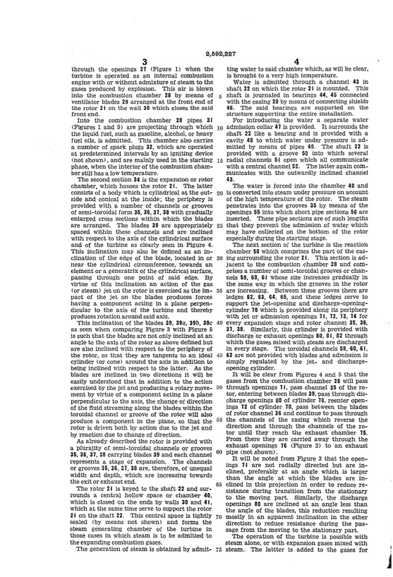
2,592,227 34 through the openings 21 (Figure 1) when the turbine is operated as an internal combustion engine with or without admixture of steam to the gasesproducedbyexplosion. Thisairisblown into the combustion chamber 28 by means of ventilator blades 29 arranged at the front end of the rotor 2| on the wall 30 which closes the said front end. For- introducing the water a separate water (Figures1and5)areprojectingthroughwhich 10 admissioncollar41isprovided. Itsurroundsthe shaft 22 like a bearing and is provided with a cavity48towhichwaterunderpressureisad mitted by means of pipes 49. The shaft 22 is provided with a groove 58 into which several Into the combustion chamber 28 pipes 3| the liquid fuel, such as gasoline, alcohol, or heavy fueloils,isadmitted. Thischamberalsocarries a number of spark plugs 32, which are operated at predetermined intervals by an igniting device (not shown), and are mainly used in the starting 15 radial channels 5| open which all communicate phase,whentheinteriorofthecombustioncham berstillhasalowtemperature. withacentralchannel52. Thelatteragaincom~ municates with the outwardly inclined channel 43. Thesecond section 34 is the expansion or rotor chamber,whichhousestherotor2|. The latter. consistsofabodywhichiscylindricalattheout 20 isconvertedintosteamunderpressureonaccount sideandconicalattheinside;theperipheryis provided with a number of channels or grooves of semi-toroidal form 35, 36, 31, 38 with gradually enlargedcrosssectionswithinwhichtheblades arearranged. Theblades39areappropriately25thattheypreventtheadmissionofwaterwhich spaced within these channels‘and are inclined with respect to the axis of the cylindrical surface and of the turbine as clearly seen in Figure 4. This inclination may also be de?ned as an in-~ clinationoftheedgeoftheblade,locatedinor 30 ingsurroundingtherotor2|. Thissectionisad jacent to the combustion chamber 28 and com prises a number of semi-toroidal grooves or chan nels 59, 66, 6| whose size increases gradually in the same way in which the grooves in the rotor near the cylindrical. circumference, towards an element or a generatrix of the cylindrical surface, passing through one point of said edge. By virtue of this inclination an action of the gas (orsteam)jetontherotorisexercisedastheim 35 areincreasing. Betweenthesegroovesthereare pact of the jet on the blades produces forces having a component acting in a plane. perpen dicular to the axis of the turbine and thereby producesrotationaroundsaidaxis. This inclination of the blades 39, 39a, 39b, 390 as seen when comparing Figure 3 with Figure 5 is such that the blades are not only inclined at an angle to the axis of the rotor as above defined but are also inclined with respect to the periphery of the rotor, so that they are tangents to an ideal cylinder (or cone) around the axis in addition to being inclined with respect to the latter. As the blades are inclined in two directions it will be easily understood that in addition to the action exercised by the jet and producing a rotary move ment by virtue of a component acting in a plane ‘perpendicular to the axis, the change of direction of the ?uid streaming along the blades within the toroidal channel or groove of the rotor will also produce a component in the plane, sovthat the rotor is driven both by action due to the jet and by reaction due to change of direction. ledges 62, 63, 64, 65, and these ledges serve to support the jet-opening and discharge-opening cylinder 10 which is provided along its periphery with jet or admission openings '|, 12, 13, 14 for every expansion stage and rotor channel 35, 36, 31, 38. “Similarly, this cylinder is provided with dischargebr exhaust openings 80, 8|, 82 through which the gases mixed with steam are discharged in every stage. The toroidal channels 59, 60, 6|, 62are not provided with blades and admission is simply regulated by the jet- and discharge openingcylinder. It will be clear from Figures 4 and 5 that the gases from the combustion chamber 28 will pass through openings 1|, pass channel 35 of the ro tor, entering between blades 39, pass through dis charge openings 80 of cylinder 13, reenter open ings 12 of cylinder 10, pass between the blades of rotor channel 36 and continue to pass through the channels of the casing which reverse the direction and through the channels of the ro tor until they reach the exhaust chamber 15. From there they are carried away through the exhaust openings 16 (Figure 2) to an exhaust As already described the rotor is provided with a plurality of semi-toroidal channels or grooves 35,36,31,38carryingblades39andeachchannel 60 pipe-(notshown). representsastageofexpansion. Thechannels or grooves 35, 36, 31, 38 are, therefore, of unequal width and depth, which are increasing'towards the exit or exhaust end. The rotor 2| is keyed to the shaft 22 and sur rounds a central hollow space or chamber 40, whichisclosedontheendsbywalls30and4|, which at the same time serve to support the rotor It will be noted from Figure 3 that the open ings ‘I.are not radially directed but are in clined, preferably at an angle which is larger than the angle at which‘ the blades are in 65 clined in this projection in order to reduce re sistance during transition from the stationary totlie- moving part. Similarly, the discharge openings 8|].are inclined at anyangle less,than the angle of the blades, this reduction resulting 2|ontheshaft22. Thiscentralspaceistightly70mostlyinanapparentinclinationintheother sealed (by means not shown) and forms the steam generating chamber of the turbine in those cases in which steam is to be admitted’to the expanding combustion gases. direction to reduce resistance during the pas sage from.the moving to the stationary part. The operation of the turbine is possible with steam alone, or with expansion gases mixed with vThegenerationofsteamisobtainedbyadmit‘ 75 steam. The lattter isadded to the gases for tingwatertosaidchamberwhich,aswillbeclear, is brought to a very high temperature. Water is admitted through a channel 43 in shaft22onwhichtherotor2|ismounted. This shaft is journaled in bearings 44, 45 connected with the casing 20 by means of connecting shields 46. The said bearings are supported on the structure supporting the entire installation. Thewaterisforcedintothechamber40and ofthehightemperatureoftherotor. Thesteam penetrates into the grooves 35 by means of the openings 55 into which short pipe sections 56 are inserted. Thesepipesectionsareofsuchlengths may, have collected on the bottom of the rotor especially during the starting stage. The next section of the turbine is the reaction chamber 58 which comprises the part of the casPDF Image | COMBINED RADIAL AND AXIAL FLOW MULTISTAGE TURBINE
PDF Search Title:
COMBINED RADIAL AND AXIAL FLOW MULTISTAGE TURBINEOriginal File Name Searched:
US2592227.pdfDIY PDF Search: Google It | Yahoo | Bing
NFT (Non Fungible Token): Buy our tech, design, development or system NFT and become part of our tech NFT network... More Info
IT XR Project Redstone NFT Available for Sale: NFT for high tech turbine design with one part 3D printed counter-rotating energy turbine. Be part of the future with this NFT. Can be bought and sold but only one design NFT exists. Royalties go to the developer (Infinity) to keep enhancing design and applications... More Info
Infinity Turbine IT XR Project Redstone Design: NFT for sale... NFT for high tech turbine design with one part 3D printed counter-rotating energy turbine. Includes all rights to this turbine design, including license for Fluid Handling Block I and II for the turbine assembly and housing. The NFT includes the blueprints (cad/cam), revenue streams, and all future development of the IT XR Project Redstone... More Info
Infinity Turbine ROT Radial Outflow Turbine 24 Design and Worldwide Rights: NFT for sale... NFT for the ROT 24 energy turbine. Be part of the future with this NFT. This design can be bought and sold but only one design NFT exists. You may manufacture the unit, or get the revenues from its sale from Infinity Turbine. Royalties go to the developer (Infinity) to keep enhancing design and applications... More Info
Infinity Supercritical CO2 10 Liter Extractor Design and Worldwide Rights: The Infinity Supercritical 10L CO2 extractor is for botanical oil extraction, which is rich in terpenes and can produce shelf ready full spectrum oil. With over 5 years of development, this industry leader mature extractor machine has been sold since 2015 and is part of many profitable businesses. The process can also be used for electrowinning, e-waste recycling, and lithium battery recycling, gold mining electronic wastes, precious metals. CO2 can also be used in a reverse fuel cell with nafion to make a gas-to-liquids fuel, such as methanol, ethanol and butanol or ethylene. Supercritical CO2 has also been used for treating nafion to make it more effective catalyst. This NFT is for the purchase of worldwide rights which includes the design. More Info
NFT (Non Fungible Token): Buy our tech, design, development or system NFT and become part of our tech NFT network... More Info
Infinity Turbine Products: Special for this month, any plans are $10,000 for complete Cad/Cam blueprints. License is for one build. Try before you buy a production license. May pay by Bitcoin or other Crypto. Products Page... More Info
| CONTACT TEL: 608-238-6001 Email: greg@infinityturbine.com | RSS | AMP |