PDF Publication Title:
Text from PDF Page: 007
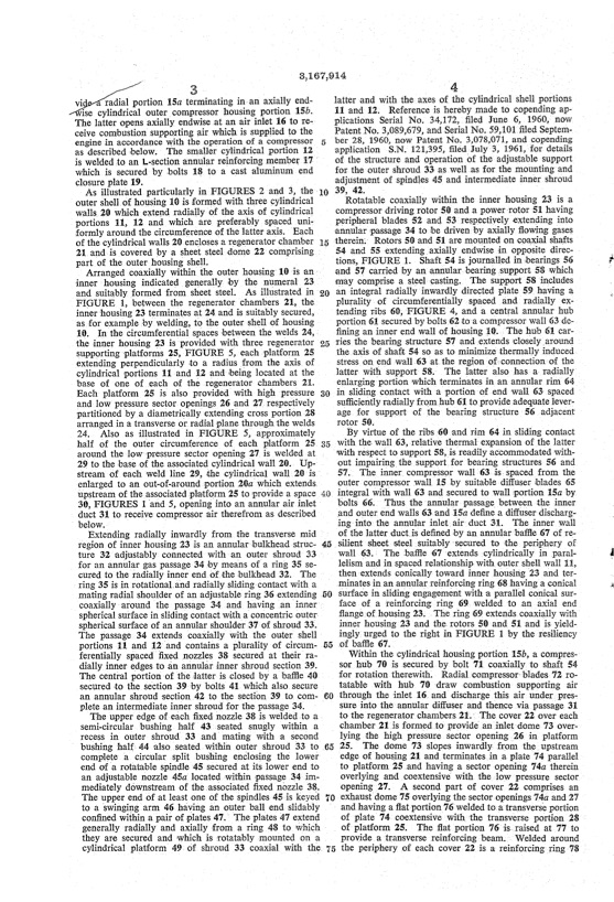
radial portion 15a term-inating in-an axially end ise cylindrical outer compressor housing portion 15b. The latter opens axially endwise at an air inlet 16 to re ceive combustion supporting air which is supplied to the engine in accordance with the operation of a compressor asdescribedbelow. Thesmallercylindricalportion12 iswelded`toan L-sectionannularreinforcingmember 1'7-' which is secured by bolts 18 to a cast aluminum end closureplate19. 4 latter and with the axes of the cylindrical shell portions 11and12. Referenceisherebymadetocopendingap plications Serial No. 34,172, tiled June 6, 1960, now Patent No. 3,089,679, and Serial No. 59,101 tiled Septem ber 28, 1960, now Patent No. 3,078,071, and copending yapplication S.N.121,395,tiledvJuly3,1961,fordetails of the structure and operation of the adjustable support for the outer shroud 33 as well yas for the mounting and adjustment of spindles 45 and intermediate inner shroud 39, 42. Rotatable coaxially within the inner housing 23 is a compressor driving rotor 50 and a power'rotor 51 having peripheral blades 52 and 53 respectively extending into annular passage 34 to be driven by axially flowing gases 3,167,914 As illustrated particularly in FIGURES 2 and 3, the outer shellof housing 10 is formed with three cylindrical walls 20 which extend radially of the axis of cylindrical portions 11, 12 and which are preferably spaced uni formlyaroundthecircumferenceofthelatteraxis. Each ofthecylindricalwalls20enclosesaregeneratorchamber 15 'therein'.>Rotors50and51aremountedoncoaxialshafts 21 and is covered by a sheet steel dome 22 comprising part of the outer housing shell. 54 and 55 extendingaxially endwise lin opposite direc tions,FIGURE 1. ShaftS4isjournalledinbearings56 and 57 carried by an «annular bearing support 53 which may comprise a steel casting. The support 58 includes Arranged coaxially within the outer housing- 10 is an> inner housing indicated generally by the numeral 23 andsuitablyformedfromsheetsteel. Asillustratedin20 anintegralradiallyinwardlydirectedplate59havinga FIGURE l,betweentheregeneratorchambers21,the inner ‘housing 23 terminates at 24 and is suitably secured, as ‘for example by welding, to the outer shell of housing 10. Inthecircumferentialspacesbetweenthewelds24, the inner housing 23 is provided with three regenerator supportingplatforms25,FIGURE 5,eachplatform25 extending perpendicularly »to a radius from the axis of cylindrical portions 11 and 12 and being located at the base of one of each of the regenerator chambers 21. Eachplatform25isalsoprovidedwithhighpressure30 inslidingcontactwithyaportionofendwall63spaced and low pressure sector openings 26 and 27 respectively partitioned by a diametrically extending cross portion 28 arrangedinatransverseorradialplanethroughthewelds 24. Also as illustrated in FIGURE 5, approximately half of the outer circumference of each platform 25 35 withtheywall63,relativethermalexpansionofthelatter around the lowl pressure sector opening 27 is welded at 29tothebaseoftheassociatedcylindricalwall20. Up-~ stream of each weld line 29, the cylindrical wall 20 is enlarged to an out-of-around portion 20a which extendsv upstreamoftheassociatedplatform25toprovideaspace40 integralwithwall63andsecuredtoWallportion15aby 30,FIGURESl'and5,openingintoanannularairinlet duct 31 to receive compressor air therefrom as described below. Y ' bolts66. Thustheannularpassagebetweentheinner _and outer end walls 63 and 15a define a diffuser discharg~ ing‘intotheannularinletairduct31. Theinnerwall of the latter iductis defined by an annular bañle 67 of re Extending radially inwardly fromk the transverse mid regionofinnerhousing23isanannular'bulkheadstruc 45 silientsheetsteelsuitablyYsecuredtotheperipheryof ture 32 adjustably connected with an outer shroud 33 for an annular gas passage 34 by means ofa ring 35 se curedtotheradiallyinnerendofthebulkhead32. The ring 35 is in rotational‘and radially sliding'contact with a matingradialshoulderofanadjustablering36extending 50 surfacein.slidingengagementwithaparallelconicalsur coaxially around the passage 34 and having kan inner sphericalsurfaceinslidingcontactwithaconcentricouterV spherical surface of an annular shoulder 37 of shroud 33. The passage 34 extends coaxially with the outer shell portions 11 and 12 and contains a plurality of circum ferentially spaced iixed Anozzles 38 secured at their ra dially inner edges to an annular inner shroud section 39. The central portion of the latter isclosed by a baffle 40 »secured to the section 39 by bolts 41 which also secure anannularshroudsection42tothesection39tocom 60throughtheinlet16vanddischargethisairvunderpres plete an intermediate inner shroud for the passage 34. The upper edge of each ñxed nozzle 38 is welded to a semi-circular bushing half 43 seated snugly within a recess in outer shroud> 33 and’mating with a second sure into the annular diffuser and thence via passage 31 to the regenerator chambers 21.` The cover 22 over each chamber 21 is formed >to provide( an inlet‘dome 73 over lying the high pressure sector opening 26 in platform bushing -half 44 lalso seated within outer shroud 33 to 65 25. The dome 73 slopes inwardly from thekupstream complete a circular split bushing enclosing the lower end of a rotatable spindle 45 secured at its lower end to an adjustable nozzle 45a located `within passage 34 im mediatelydownstreamoftheassociatedfixednozzle33. Theupperendofatleastoneofthespindles45iskeyed 10exhaustdome75overlyingthesectoropenings74aand27 to a swinging arm 46 having an outer ball end slidably confined within a pair of :plates 47.' The plates 47 extend generallyradiallyandaxiallyfromaring48towhich theyaresecuredandwhichisrotatablymountedona cylindrical platform 49 of shroud 33 coaxial with the and having a flatportion 76 welded to a transverse portion of plate 74 coextensive with the transverse portion 28 ofplatform25. Theñatportion76is>raisedat77to provideatransversereinforcingbeam. Weldedaround the periphery of each cover 22 is a reinforcing ring 78 plurality of circum-ferentially spaced and radially ex tending ribs 60, FIGURE 4, and a central annular hub portion 61 secured by bolts 62 to a compressor wall 63 de ñninganinnerendwallofhousing10i. Thehub61car ries the bearing structure 57 and extends closelyaround the axis of shaft 54 so as to minimize thermally induced stress on end wall 63 at the region ofvconnection of the latterwithsupportS8. ThelatteralsohasaVradially enlargin-g portion vwhich terminates in an annular rim 64 suñicientlyradiallyfromhub61toprovideadequatelever age for support of the bearing structure 56 adjacent rotor 50. By virtue of the ribs 60 and rim 64 in sliding contact ‘with respect to support 58, is readily accommodated with out impairingthe support for bearing structures 56 and 57. TheinnercompressorWall63`isvspacedfromthe outer compressor wall 15 by suitable diffuser blades 65 wall 63.l The baffle »67 >extends cylindrically in paral lelism and in spaced relationship with outer shell wall 11, then'extends conically toward inner housing >23 and ter~ minates in an annular reinforcing ring 68 having a conical face of a reinforcing ring 69,ywelded to an axial end flangeofhousing23. Thering69extendscoaxiallywith inner housing 23 and the. rotors 50 and 51 and is yield inglyurgedtotherightinFIGURE lbytheresiliency of baffle 67. . Within the cylindrical housing portion 15b, a compres~ sor hub 70 is secured by bolt 71 coaxially to» shaft 54 forrotationtherewith. Radialcompressor'blades72ro tatable with hub 70 >draw combustion supporting air edge of housing 21 and terminates in a plate '74 parallel to platform 25 .and having a sector opening 74a therein overlying and coextensive with the low pressure sector opening27. A secondpartofcover22comprisesanPDF Image | GAS TURBINE ENGINE HOUSING
PDF Search Title:
GAS TURBINE ENGINE HOUSINGOriginal File Name Searched:
US3167914.pdfDIY PDF Search: Google It | Yahoo | Bing
NFT (Non Fungible Token): Buy our tech, design, development or system NFT and become part of our tech NFT network... More Info
IT XR Project Redstone NFT Available for Sale: NFT for high tech turbine design with one part 3D printed counter-rotating energy turbine. Be part of the future with this NFT. Can be bought and sold but only one design NFT exists. Royalties go to the developer (Infinity) to keep enhancing design and applications... More Info
Infinity Turbine IT XR Project Redstone Design: NFT for sale... NFT for high tech turbine design with one part 3D printed counter-rotating energy turbine. Includes all rights to this turbine design, including license for Fluid Handling Block I and II for the turbine assembly and housing. The NFT includes the blueprints (cad/cam), revenue streams, and all future development of the IT XR Project Redstone... More Info
Infinity Turbine ROT Radial Outflow Turbine 24 Design and Worldwide Rights: NFT for sale... NFT for the ROT 24 energy turbine. Be part of the future with this NFT. This design can be bought and sold but only one design NFT exists. You may manufacture the unit, or get the revenues from its sale from Infinity Turbine. Royalties go to the developer (Infinity) to keep enhancing design and applications... More Info
Infinity Supercritical CO2 10 Liter Extractor Design and Worldwide Rights: The Infinity Supercritical 10L CO2 extractor is for botanical oil extraction, which is rich in terpenes and can produce shelf ready full spectrum oil. With over 5 years of development, this industry leader mature extractor machine has been sold since 2015 and is part of many profitable businesses. The process can also be used for electrowinning, e-waste recycling, and lithium battery recycling, gold mining electronic wastes, precious metals. CO2 can also be used in a reverse fuel cell with nafion to make a gas-to-liquids fuel, such as methanol, ethanol and butanol or ethylene. Supercritical CO2 has also been used for treating nafion to make it more effective catalyst. This NFT is for the purchase of worldwide rights which includes the design. More Info
NFT (Non Fungible Token): Buy our tech, design, development or system NFT and become part of our tech NFT network... More Info
Infinity Turbine Products: Special for this month, any plans are $10,000 for complete Cad/Cam blueprints. License is for one build. Try before you buy a production license. May pay by Bitcoin or other Crypto. Products Page... More Info
| CONTACT TEL: 608-238-6001 Email: greg@infinityturbine.com | RSS | AMP |