PDF Publication Title:
Text from PDF Page: 004
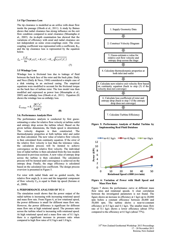
3.4 Tip Clearance Loss The tip clearance is modelled as an orifice with shear flow inside the passage (Ghosh et al., 2011). A study by Baines shows that radial clearance has strong influence on the exit flow condition compared to axial clearance (Moustapha et al., 2003). An in-depth examination has showed that the variations of efficiency with axial and radial clearance are not independent as some cross-couplings exist. The cross coupling coefficient was represented with a coefficient, Ka,r and the tip clearance loss is represented by the equation below. U1Zr(KCKCK CC tip 8 aaa rrr a,r arar 3.5 Windage Loss 3. Guess-estimate a value for relative exit flow velocity and entropy drop across the stage 4. Calculate thermodynamic properties at both inlet and outlet 6. Calculate loss coefficient of rotor and entropy drop (back to step 3 if the entropy drop does not converge) 7. Calculate Turbine Efficiency Figure 5: Performance Analysis of Radial Turbine by Implementing Real Fluid Database Windage loss is frictional loss due to leakage of fluid between the back face of the rotor and the back plate. Daily and Nece (Daily & Nece, 1960) considered a simple case of a disk rotating in an enclosed casing. The empirical equations were modified to account for the frictional torque on the back face of turbine rotor. The loss model was then modified and expressed as power loss (Moustapha et al., 2003) and enthalpy loss (Ghosh et al., 2011). Equation (8) shows the windage loss as enthalpy loss. w i n d a g e (8) (7) 1. Supply Geometry Data 2. Construct Velocity Diagram 5. Calculate new relative exit velocity flow based on continuity equation (back to step (3) if the velocity does not converge) k U3r2 11 The performance analysis is conducted by first guess- estimating a value for relative flow velocity at turbine outlet and entropy drop across the turbine wheel. Based on the given turbine dimensions, the blade speed is determined. The velocity diagram is then constructed. The thermodynamic properties at both turbine inlet and outlet are then calculated. The new value of relative flow velocity is then calculated from continuity equation. If the error of the relative flow velocity is less than the tolerance value, the calculation process will be iterated to achieve convergence on the relative flow velocity. The individual loss of radial turbine is then calculated from the loss models discussed in previous sections. A new value of entropy drop across the turbine is then calculated. The calculation process will be iterated until convergence is achieved on the entropy drop. Finally, the stage efficiency is calculated based on the calculated loss coefficient. The design process overview is presented in Figure 5. For rotor with radial blade and no guided nozzle, the relative flow angle β1 is zero and the tangential component of flow velocity Cθ1 is equal to blade tip speed (Serrano et al., 2008). 4. PERFORMANCE ANALYSIS OF TC-1 The simulation result shows that the power output of the radial turbine is increasing with increasing rotational speed and mass flow rate. From Figure 6, at low rotational speed, the power difference is small for different mass flow rate. However, the power difference is significant for different mass flow rate at high rotational speed. The pressure ratio across the turbine wheel is increasing with rotational speed. At high rotational speed and a mass flow rate of 0.1 kg/s. there is a significant increase in pressure ratio when compared to high flow rates of 0.5 kg/s and 1.0 kg/s. f 2 m W 2 2 3.6. Performance Analysis Flow 12 10 8 6 4 2 0 m=0.1 kg/s m=0.5kg/s m=1kg/s 0 10 20 30 40 50 Rotational Speed x1000 (rev/min) Figure 6: Variation of Power with Shaft Speed and Mass Flow Rate Figure 7 shows the performance curve at different mass flow rates and rotational speeds. A clear correlation between the investigated parameters is not found. The figure shows an increase in efficiency at 1 kg/s up to 20,000 rpm before a constant efficiency between 20,000 and 50,000 rpm. The turbine shows a near-to-constant efficiency at 0.5 kg/s and 0.1 kg/s. The smaller mass flow rate of 0.1 kg/s shows a lower efficiency (about 55%) compared to the efficiency at 0.5 kg/s (about 77%). 35th New Zealand Geothermal Workshop: 2013 Proceedings 17 – 20 November 2013 Rotorua, New Zealand Power (kW)PDF Image | TURBOCHARGER AS TURBO-EXPANDER FOR ORGANIC RANKINE CYCLE
PDF Search Title:
TURBOCHARGER AS TURBO-EXPANDER FOR ORGANIC RANKINE CYCLEOriginal File Name Searched:
Wong_Final.pdfDIY PDF Search: Google It | Yahoo | Bing
NFT (Non Fungible Token): Buy our tech, design, development or system NFT and become part of our tech NFT network... More Info
IT XR Project Redstone NFT Available for Sale: NFT for high tech turbine design with one part 3D printed counter-rotating energy turbine. Be part of the future with this NFT. Can be bought and sold but only one design NFT exists. Royalties go to the developer (Infinity) to keep enhancing design and applications... More Info
Infinity Turbine IT XR Project Redstone Design: NFT for sale... NFT for high tech turbine design with one part 3D printed counter-rotating energy turbine. Includes all rights to this turbine design, including license for Fluid Handling Block I and II for the turbine assembly and housing. The NFT includes the blueprints (cad/cam), revenue streams, and all future development of the IT XR Project Redstone... More Info
Infinity Turbine ROT Radial Outflow Turbine 24 Design and Worldwide Rights: NFT for sale... NFT for the ROT 24 energy turbine. Be part of the future with this NFT. This design can be bought and sold but only one design NFT exists. You may manufacture the unit, or get the revenues from its sale from Infinity Turbine. Royalties go to the developer (Infinity) to keep enhancing design and applications... More Info
Infinity Supercritical CO2 10 Liter Extractor Design and Worldwide Rights: The Infinity Supercritical 10L CO2 extractor is for botanical oil extraction, which is rich in terpenes and can produce shelf ready full spectrum oil. With over 5 years of development, this industry leader mature extractor machine has been sold since 2015 and is part of many profitable businesses. The process can also be used for electrowinning, e-waste recycling, and lithium battery recycling, gold mining electronic wastes, precious metals. CO2 can also be used in a reverse fuel cell with nafion to make a gas-to-liquids fuel, such as methanol, ethanol and butanol or ethylene. Supercritical CO2 has also been used for treating nafion to make it more effective catalyst. This NFT is for the purchase of worldwide rights which includes the design. More Info
NFT (Non Fungible Token): Buy our tech, design, development or system NFT and become part of our tech NFT network... More Info
Infinity Turbine Products: Special for this month, any plans are $10,000 for complete Cad/Cam blueprints. License is for one build. Try before you buy a production license. May pay by Bitcoin or other Crypto. Products Page... More Info
| CONTACT TEL: 608-238-6001 Email: greg@infinityturbine.com | RSS | AMP |