PDF Publication Title:
Text from PDF Page: 012
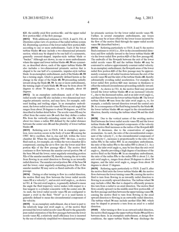
US 2013/0192219Al Aug.1,2013 62b, the middle axial ?oW portion 620, and the upper radial ?oWportion62d,ofthe?oWpassage. [0031] WithadditionalreferencetoFIGS.2and3,FIG.4 thereinmaybeatleastoffsetbytheloWerlossesincurredby illustratesaplanvieWofaportionoftheradialturbinesystem 12,illustratingaportionoftheloWerradial?oW portion62b, according to one or more embodiments. Each of the loWer turbineblades48may includeatWo-dimensionalprismatic section,Whichmay beshapedtobeonehalfofasymmetric, generally crescent-shaped, impulse-style turbine blade or “bucket.” Although not shoWn, in one or more embodiments Where the upper and loWer turbine blades 48, 50 are symmet ric, as described above, each of the upper turbine blades 50 also includes a tWo-dimensional prismatic section that is shaped to be one halfof a symmetric, impulse-style turbine blade. In an exemplary embodiment, each ofthe blades 48, 50 has a turning angle, Which is generally de?ned herein as the change in the slope of the blade 48, 50 proceeding radially inWard along the blade 48, 50. In one or more embodiments, theturningangleofeachblade48,50may befromabout50 degrees to about 70 degrees, or, for example, about 60 degrees. the?oW ofthemotive?uidthroughtheupperradialnoZZle vanes 54 (describedbeloW). [0036] ReferringparticularlytoFIGS.2and3,themotive ?uidcontinuestosWirl(i.e.,?oWinthecircumferentialdirec tion)and?oW radially-inWardtotheloWerturbineblades48 viatheloWerradial?oW portion62bofthe?oW passage62. The endWalls of the ?oWpath betWeen the exit of the loWer radial noZZle vanes 52 and the turbine blades 48 may be contouredtoachieveapproximatelyconstantradialvelocity. Inanexemplaryembodiment,the?oWpathareasoftheloWer radial ?oW portion 62b ofthe ?oW passage may be approxi mately constant at all radial locations betWeen the exit of the noZZlevanes52andtheinletoftheturbineblades48,thereby substantially avoiding radial acceleration. For example, the loWer radial ?oW portion 62b may increase in thickness to offsetthereducedcircumferenceproceedingradially-inWard. [0037] AsshoWninFIG.4,themotive?uidmayproceed toWard the loWer turbine blades 48 at an increased velocity [0032] Inanexemplaryembodiment,eachoftheloWer C2,duetothedecreasedradius,andataninletsWirlangle(x2 radial noZZle vanes 52 also includes a tWo-dimensional rect angular prismatic section, and may have, for example, radi used leading and trailing edges. In an exemplary embodi ment, the loWer radial noZZle vanes 52 have an exit angle that ranges from about 20 degrees to about 30 degrees, as Will be describedinfurtherdetailbeloW. The noZZlevanes 52 may be offset from the center axis 26 such that they de?ne a radius 53a from the vertically-extending center axis 26, Which is about tWo times a radius 53b de?ned by the radial distance betWeen the center axis 26 and the plurality of loWer turbine blades 48. [0033] ReferringnoWtoFIGS.1-4,inexemplaryopera tion,WavemotionoccursinthebodyofWater18causingthe OWC 14tooscillate,thatis,riseandfal,WithintheWave chamber22.WhentheoscillatingOWC 14rises,amotive ?uid such as,forexample, air,WithintheWave chamber 22 is compressed,causingtheairto?oW intotheloWeraxial?oW portion 62a of the ?oW passage 62a-d. The motive ?uid continues to ?oW betWeen the annular curved portion 340 of the base 34 and the loWer, outer angularly-extending portion 32a oftheannularmember 32,therebycausingtheairtoturn from ?oWing in an axial direction to ?oWing in an inWardly radialdirection.Theannularcurvedportion340ofthebase34 and the loWer, outer angularly-extending portion 32a of the annularmember32may serveas?aredendWallsofthe?oW passage. [0034] Duringorafterturningto?oWinaradialdirection, the motive ?uid may ?oW betWeen the loWer radial noZZle vanes 52 at a velocity C 1and an exit sWirl angle (x1, as shoWn inFIG. 4.The exitsWirlangle(x1isgenerallyde?nedtomean the angle the ?uid trajectory vector makes With respect to a line tangent to a cylinder concentric With the center axis 26. As such, the loWer radial noZZle vanes 52 are con?gured to impart a sWirl in the ?uid. “SWir ” as it is used herein is generally de?ned to mean the circumferential component of thevelocity. [0035] Inanexemplaryembodiment,dueatleastinpartto the relatively large exit sWirl angle al of the motive ?uid proximaltheloWerradialnoZZlevanes52andtothegenerally pureradialorientationofthe?oW passagesbetWeentheloWer noZZle vanes 52, a relatively small e?iciency loss is incurred bytheuseofrelativelysimpli?edtWo-dimensionalrectangu andthen?oW betWeentheloWerturbineblades48.The loWer turbine blades 48 turn from the inlet sWirl angle (x2 to, for example, a radially-inWard direction toWard the central axis 26.As aconsequenceofthe?uidbeingturnedbytheblade48, the loWer turbine blades 48 are urged in the circumferential direction,therebyrotatingtheturbineWheel36andtheshaft 38. [0038] DuetothevorticalnatureofthesWirlingmotive ?uid betWeen the loWer radial noZZle vanes 52 and the loWer turbine blades 48, the tangential components of the velocity ofthe motive ?uid increases as the radius ofthe ?oWpath 62b (FIG.2)decreases,duetotheconservationofangular momentum.As such,theratioofthecircumferentialcompo nent of the velocity C1 to the circumferential component of the velocity C2 increases is proportionally to the ratio of the radius 53a to the radius 53b. In an exemplary embodiment, theratiooftheradius53a totheradius53b isabout2:1.As a result,theinletsWirlangle(x2may belessthantheexitsWirl angle(x1,therebyprovidingahighdegreeofincidenceofthe motive ?uid on the blades 48. In an exemplary embodiment, the ratio of the radius 53a to the radius 53b is about 2:1, the exit sWirl angle (x1 ranges from about 20 degrees to about 30 degrees, and the inlet sWirl angle (x2 ranges from about 10 degrees to about 15 degrees. [0039] ReferringagainparticularlytoFIGS.2and3,after themotive?uidexitstheloWerturbineblades48,themotive ?oWsbetWeentheloWerturningvanes56,causingthemotive ?uid to turn from ?oWing in an inWardly radial direction to ?oWing in an axially upWard direction. The turbine Wheel 36 may includea?llet3611thatisshapedtoe?icientlypromote this turn from a radial to an axial direction. The motive ?uid ?oWs axiallyupWard viathemiddle axial?oW portion620 of the?oW passageandthenbetWeentheupperturningvanes58, causing the motive ?uid to turn from ?oWing in the axial upWard direction to ?oWing in an outWardly radial direction. The turbine Wheel 36 may include another ?llet 36b, Which may be shaped to promote a turn from an axial to a radial direction. [0040] Afterturningto?oWinanoutWardradialdirection, themotive?uidengagestheupperturbineblades50and?oWs betWeen them. In an exemplary embodiment, at design ?oW conditions, the upper turbine blades 50 may discharge the lar prismatic sections for the loWer radial noZZle vanes 52. Further, in several exemplary embodiments, any lossesPDF Image | ENERGY CONVERSION SYSTEM WITH RADIAL FLOW TURBINE
PDF Search Title:
ENERGY CONVERSION SYSTEM WITH RADIAL FLOW TURBINEOriginal File Name Searched:
US20130192219.pdfDIY PDF Search: Google It | Yahoo | Bing
NFT (Non Fungible Token): Buy our tech, design, development or system NFT and become part of our tech NFT network... More Info
IT XR Project Redstone NFT Available for Sale: NFT for high tech turbine design with one part 3D printed counter-rotating energy turbine. Be part of the future with this NFT. Can be bought and sold but only one design NFT exists. Royalties go to the developer (Infinity) to keep enhancing design and applications... More Info
Infinity Turbine IT XR Project Redstone Design: NFT for sale... NFT for high tech turbine design with one part 3D printed counter-rotating energy turbine. Includes all rights to this turbine design, including license for Fluid Handling Block I and II for the turbine assembly and housing. The NFT includes the blueprints (cad/cam), revenue streams, and all future development of the IT XR Project Redstone... More Info
Infinity Turbine ROT Radial Outflow Turbine 24 Design and Worldwide Rights: NFT for sale... NFT for the ROT 24 energy turbine. Be part of the future with this NFT. This design can be bought and sold but only one design NFT exists. You may manufacture the unit, or get the revenues from its sale from Infinity Turbine. Royalties go to the developer (Infinity) to keep enhancing design and applications... More Info
Infinity Supercritical CO2 10 Liter Extractor Design and Worldwide Rights: The Infinity Supercritical 10L CO2 extractor is for botanical oil extraction, which is rich in terpenes and can produce shelf ready full spectrum oil. With over 5 years of development, this industry leader mature extractor machine has been sold since 2015 and is part of many profitable businesses. The process can also be used for electrowinning, e-waste recycling, and lithium battery recycling, gold mining electronic wastes, precious metals. CO2 can also be used in a reverse fuel cell with nafion to make a gas-to-liquids fuel, such as methanol, ethanol and butanol or ethylene. Supercritical CO2 has also been used for treating nafion to make it more effective catalyst. This NFT is for the purchase of worldwide rights which includes the design. More Info
NFT (Non Fungible Token): Buy our tech, design, development or system NFT and become part of our tech NFT network... More Info
Infinity Turbine Products: Special for this month, any plans are $10,000 for complete Cad/Cam blueprints. License is for one build. Try before you buy a production license. May pay by Bitcoin or other Crypto. Products Page... More Info
| CONTACT TEL: 608-238-6001 Email: greg@infinityturbine.com | RSS | AMP |