PDF Publication Title:
Text from PDF Page: 012
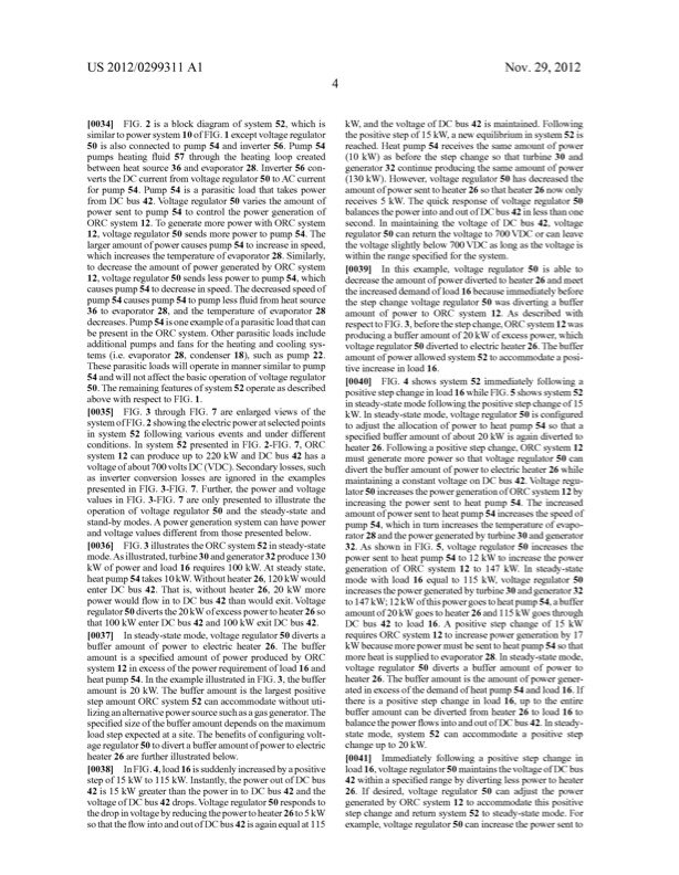
US 2012/0299311Al Nov.29,2012 [0034] FIG.2isablockdiagramofsystem52,whichis kW,andthevoltageofDCbus42ismaintained.Following similartopowersystem10ofFIG.1exceptvoltageregulator 50 is also connected to pump 54 and inverter 56. Pump 54 pumps heating ?uid 57 through the heating loop created between heat source 36 and evaporator 28. Inverter 56 con vertstheDC currentfromvoltageregulator50toAC current forpump 54.Pump 54isaparasiticloadthattakespower fromDC bus42.Voltageregulator50variestheamountof power sent to pump 54 to control the power generation of ORC system12.TogeneratemorepowerwithORC system 12,voltageregulator50sendsmorepowertopump54.The largeramountofpowercausespump 54toincreaseinspeed, whichincreasesthetemperatureofevaporator28.Similarly, withintherangespeci?edforthesystem. todecreasetheamountofpowergeneratedbyORC system 12, voltage regulator 50 sends less power to pump 54, which causespump 54todecreaseinspeed.Thedecreasedspeedof pump 54causespump 54topump less?uidfromheatsource 36 to evaporator 28, and the temperature of evaporator 28 decreases.Pump 54isoneexampleofaparasiticloadthatcan bepresentintheORC system.Otherparasiticloadsinclude additional pumps and fans for the heating and cooling sys tems (i.e. evaporator 28, condenser 18), such as pump 22. These parasitic loads will operate in manner similar to pump 54andwillnotaffectthebasicoperationofvoltageregulator 50. The remaining features of system 52 operate as described above with respect to FIG. 1. [0039] Inthisexample,voltageregulator50isableto decrease the amount of power diverted to heater 26 and meet theincreaseddemandofload16becauseimmediatelybefore the step change voltage regulator 50 was diverting a buffer amountofpowertoORC system12.Asdescribedwith respecttoFIG.3,beforethestepchange,ORC system12was producingabufferamountof20kW ofexcesspower,which voltage regulator 50 diverted to electric heater 26. The buffer amount of power allowed system 52 to accommodate a posi tive increase in load 16. [0040] FIG.4showssystem52immediatelyfollowinga positive step change in load 16 while FIG. 5 shows system 52 insteady-statemodefollowingthepositivestepchangeof15 kW. In steady-state mode, voltage regulator 50 is con?gured to adjust the allocation of power to heat pump 54 so that a speci?edbufferamountofabout20kW isagaindivertedto heater26.Followingapositivestepchange,ORC system12 must generate more power so that voltage regulator 50 can divert the buffer amount of power to electric heater 26 while maintainingaconstantvoltageonDC bus42.Voltageregu lator50increasesthepowergenerationofORC system12by increasing the power sent to heat pump 54. The increased amountofpowersenttoheatpump 54increasesthespeedof pump 54,whichinturnincreasesthetemperatureofevapo rator28andthepowergeneratedbyturbine30andgenerator 32.AsshowninFIG.5,voltageregulator50increasesthe powersenttoheatpump 54to12kW toincreasethepower generation of ORC system 12 to 147 kW. In steady-state mode with load 16 equal to 115 kW, voltage regulator 50 increasesthepowergeneratedbyturbine30andgenerator32 to147kW; 12kW ofthispowergoestoheatpump 54,abuffer amountof20kW goestoheater26and115kW goesthrough DC bus42toload16.A positivestepchangeof15kW [0035] FIG.3throughFIG.7areenlargedviewsofthe systemofFIG.2showingtheelectricpoweratselectedpoints in system 52 following various events and under different conditions. In system 52 presented in FIG. 2-FIG. 7, ORC system12canproduceupto220kW andDC bus42hasa voltageofabout700voltsDC (VDC).Secondarylosses,such as inverter conversion losses are ignored in the examples presented in FIG. 3-FIG. 7. Further, the power and voltage values in FIG. 3-FIG. 7 are only presented to illustrate the operation of voltage regulator 50 and the steady-state and stand-bymodes.A powergenerationsystemcanhavepower andvoltagevaluesdifferentfromthosepresentedbelow. [0036] FIG.3illustratestheORCsystem52insteady-state mode.Asillustrated,turbine30andgenerator32produce130 kW ofpowerandload16requires100kW.Atsteadystate, heatpump54takes10kW.Withoutheater26,120kW would enterDC bus42.Thatis,withoutheater26,20kW more powerwould?ow intoDC bus42thanwouldexit.Voltage regulator50divertsthe20kW ofexcesspowertoheater26so that100kW enterDC bus42and100kW exitDC bus42. [0037] Insteady-statemode,voltageregulator50divertsa requiresORCsystem12toincreasepowergenerationby17 buffer amount of power to electric heater 26. The buffer amount isa speci?ed amount ofpower produced by ORC system 12 in excess of the power requirement of load 16 and heatpump 54.IntheexampleillustratedinFIG.3,thebuffer amount is 20 kW. The buffer amount is the largest positive stepamountORC system52canaccommodatewithoututi liZing an alternative power source such as a gas generator. The speci?edsiZeofthebufferamountdependsonthemaximum load step expected at a site. The bene?ts of con?guring volt age regulator 50 to divert a buffer amount ofpower to electric heater 26 are further illustrated below. [0038] InFIG.4,load16issuddenlyincreasedbyapositive stepof15kW to115kW.Instantly,thepoweroutofDC bus 42is15kW greaterthanthepowerintoDCbus42andthe voltageofDC bus42drops.Voltageregulator50respondsto thedropinvoltagebyreducingthepowertoheater26to5kW sothatthe?owintoandoutofDC bus42isagainequalat115 kW becausemorepowermustbesenttoheatpump54sothat moreheatissuppliedtoevaporator28.Insteady-statemode, voltage regulator 50 diverts a buffer amount of power to heater 26. The buffer amount is the amount of power gener atedinexcessofthedemandofheatpump 54andload16.If thereisapositivestepchangeinload16,uptotheentire buffer amount can be diverted from heater 26 to load 16 to balancethepower?owsintoandoutofDC bus42.Insteady state mode, system 52 can accommodate a positive step change up to 20 kW. [0041] Immediatelyfollowingapositivestepchangein load16,voltageregulator50maintainsthevoltageofDC bus 42withinaspeci?edrangebydivertinglesspowertoheater 26.Ifdesired,voltageregulator50canadjustthepower generatedbyORC system12toaccommodatethispositive step change and return system 52 to steady-state mode. For example,voltageregulator50canincreasethepowersentto thepositivestepof15kW, anew equilibriuminsystem52 is reached. Heat pump 54 receives the same amount of power (10 kW) as before the step change so that turbine 30 and generator 32 continue producing the same amount of power (130 kW). However, voltage regulator 50 has decreased the amountofpowersenttoheater26sothatheater26nowonly receives5kW.Thequickresponseofvoltageregulator50 balancesthepowerintoandoutofDC bus42inlessthanone second.InmaintainingthevoltageofDC bus42,voltage regulator50canreturnthevoltageto700VDC orcanleave thevoltageslightlybelow700VDC aslongasthevoltageisPDF Image | ORC Cycle Load
PDF Search Title:
ORC Cycle LoadOriginal File Name Searched:
US20120299311.pdfDIY PDF Search: Google It | Yahoo | Bing
NFT (Non Fungible Token): Buy our tech, design, development or system NFT and become part of our tech NFT network... More Info
IT XR Project Redstone NFT Available for Sale: NFT for high tech turbine design with one part 3D printed counter-rotating energy turbine. Be part of the future with this NFT. Can be bought and sold but only one design NFT exists. Royalties go to the developer (Infinity) to keep enhancing design and applications... More Info
Infinity Turbine IT XR Project Redstone Design: NFT for sale... NFT for high tech turbine design with one part 3D printed counter-rotating energy turbine. Includes all rights to this turbine design, including license for Fluid Handling Block I and II for the turbine assembly and housing. The NFT includes the blueprints (cad/cam), revenue streams, and all future development of the IT XR Project Redstone... More Info
Infinity Turbine ROT Radial Outflow Turbine 24 Design and Worldwide Rights: NFT for sale... NFT for the ROT 24 energy turbine. Be part of the future with this NFT. This design can be bought and sold but only one design NFT exists. You may manufacture the unit, or get the revenues from its sale from Infinity Turbine. Royalties go to the developer (Infinity) to keep enhancing design and applications... More Info
Infinity Supercritical CO2 10 Liter Extractor Design and Worldwide Rights: The Infinity Supercritical 10L CO2 extractor is for botanical oil extraction, which is rich in terpenes and can produce shelf ready full spectrum oil. With over 5 years of development, this industry leader mature extractor machine has been sold since 2015 and is part of many profitable businesses. The process can also be used for electrowinning, e-waste recycling, and lithium battery recycling, gold mining electronic wastes, precious metals. CO2 can also be used in a reverse fuel cell with nafion to make a gas-to-liquids fuel, such as methanol, ethanol and butanol or ethylene. Supercritical CO2 has also been used for treating nafion to make it more effective catalyst. This NFT is for the purchase of worldwide rights which includes the design. More Info
NFT (Non Fungible Token): Buy our tech, design, development or system NFT and become part of our tech NFT network... More Info
Infinity Turbine Products: Special for this month, any plans are $10,000 for complete Cad/Cam blueprints. License is for one build. Try before you buy a production license. May pay by Bitcoin or other Crypto. Products Page... More Info
| CONTACT TEL: 608-238-6001 Email: greg@infinityturbine.com | RSS | AMP |