PDF Publication Title:
Text from PDF Page: 011
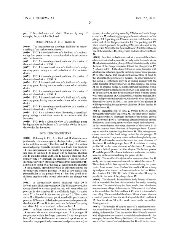
US 2011/0308967A1 Dec.22,2011 part of this disclosure and Which illustrate, by Way of example, the principles disclosed. DESCRIPTION OF THE FIGURES [0049] Theaccompanyingdrawingsfacilitateanunder standingofthevariousembodiments. [0050] FIG.1issectionalvieWofa?uidendofarecipro cating frac pump having a cavitation device in accordance Withthisinvention. [0051] FIG.2isanenlargedsectionalvieWofaportionof the cavitation device of FIG. 1. [0052] FIG.3isasectionalvieWofa?uidendofarecip rocating pump having a second embodiment of a cavitation device. [0053] FIG.4isanenlargedsectionalvieWofaportionof the cavitation device of FIG. 3. [0054] FIG.5isasectionalvieWofa?uidendofarecip rocating pump having another embodiment of a cavitation device. [0055] FIG.6isanenlargedsectionalvieWofaportionof the cavitation device of FIG. 5. [0056] FIG.7isasectionalvieWofa?uidendofarecip rocating pump having another embodiment of a cavitation device. [0057] FIG.8isanenlargedsectionalvieWofaportionof the cavitation device of FIG. 7. [0058] FIG.9isaschematicvieWillustratingacentrifugal pump having a cavitation device in accordance With this invention. [0059] FIG.10isaschematicvieWofacentrifugalpump having another embodiment of a cavitation device in accor dance With this invention. DETAILED DESCRIPTION [0060] ReferringtoFIG.1,a?uidend11illustratesone portionofareciprocatingpump ofatypethatistypicallyused in the Well frac industry. The ?uid end 11 is part of a surface mounted pump, typically mounted on a truck. The ?uid end 11 isnot submersed in the ?uid to be pumped; rather a ?oW line leads to the ?uid 11 to convey itto be pumped. The ?uid end 11 includes a ?uid end block 13 having a chamber 15. A plunger bore 17 intersects the chamber 15 on one side. A dischargevalveportorpassage19leadsfromthechamber15; a suction on inlet port or passage 21 leads from the chamber 15 in a generally opposite direction. In this embodiment, the discharge and suction passages 19 and 21 are coaxial and perpendicular to the plunger bore 17, but they could be at differentanglesrelativetoeachotherandtotheplungerbore 17. shoWn).A sealorpackingassembly27islocatedinthe?ange connector 23 and sealingly engages the outer diameter of the plunger25.A packingnut29securestointernalthreadsatthe outer end of the ?ange connector 23. The packing nut 29, Whenrotated,preloadsthepacking27toprovideasealforthe plunger25.Normally,the?uidendblock13Willhavethreeor ?veofthechambers15,plungers25,andsetsofvalves20and 22. [0063] Ina?rstembodiment,adevicetoretardtheeffects of cavitation includes a sacri?cial body in the form of a sleeve 31,Whichsurroundstheplunger25and?tsstationarilyWithin the bore of the ?ange connector 23 and the plunger bore 17. As shoWninFIG.2,thesleeve31hasaninnerdiameterWith a turbulence enhancing pro?le including one or more grooves 35orothershapesthatcandisruptlaminar?oW of?uid.In this example, the groove 35 is helical. The inner diameter of the sleeve 31 optionally may be in sliding contact With the outer diameter of the plunger 25. In this example, the sleeve 31 has an external ?ange 33 on its outer end that mates With a shoulder Within the ?ange connector 23. The inner end or rim 40 ofthe sleeve 31 may be substantially ?ush With the inside Wallofthechamber15.Consequently,Whentheplunger25is inthefullpoWerstrokeposition,WhichWillbetotherightof the position shoWn in FIG. 1, the inner end of the plunger 25 Will be protruding farther into the chamber 15 than the rim 40 ofthe sleeve 31. [0064] ReferringstiltoFIG.2,bypassports37extend throughthesideWallofthesleeve31.Theinnerendofeachof the bypass ports 37 intersects one turn of the helical groove 35. The bypass ports 37 are spaced circumferentially around thesleeve31andalongaportionofthelengthofthesleeve31. In this embodiment, the outer diameter of the sleeve 31 is smallerthantheinnerdiameteroftheplungerbore17,creat ing an annulus surrounding the sleeve 31. This arrangement causes some of the ?uid being pushed by the plunger 25 duringtheinWardorpoWer stroketo?oW throughthebypass ports 37 and into the annulus betWeen the outer diameter of thesleeve31andtheplungerbore17.A turbulencecreating pro?le 38 on the outer diameter of the sleeve 31 may also include a helical groove or other shapes. The helical groove 35 and the ports 37 enhance turbulence and cause cavitation to occur in the annulus during the poWer stroke. [0065] Thesacri?cialbodyincludesanumberofneedles39 (only one shoWn) mounted around rim 40 of the sleeve 31. The turbulent ?uid ?oWing out the annulus during the poWer stroke ?oWs around them. Each ofthe needles 39 has a sharp tip and protrudes inWard or doWnstream from the rim 40 into the chamber 15 (FIG. 1). Each of the needles 39 may be parallel to the axis of the plunger bore 17. [0066] Thesleeve31isasacri?cialbodyformedofamate rial or materials that has characteristics for easily releasing locatedinthedischargepassage19.Thedischargevalve20is electrons.Thematerialmaybe,forexample,Zinc,aluminum, magnesium oralloysofthesemetals.Thismaterialisofaless noble metal than the ?uid end block 13, Which is formed of a [0061] A schematically shoWn discharge valve 20 is spring-biased to a closed position, and Will open When the pressure in the chamber 15 is su?iciently high. A suction valve 22 is located in the suction passage 21. The suction valve 22 isbiased to a closed position and Will open When the pressuredifferentialoftheintakepressureoverthepressurein the chamber 15 is su?icient to overcome the bias of the spring and alloW ?uid to be admitted to the chamber 15. [0062] A ?angeconnector23securestothe?uidendblock 13 on one side around the plunger bore 17. A plunger 25 reciprocates Within the ?ange connector 23 and the plunger bore 17 and is strokedbetWeen an outer intake position and an inner discharge position by a conventional poWer source (not steel alloy. The material of the sleeve 31 has a loWer electro chemicalpotentialthanthesteelalloyofthe?uidendblock 13, thus the sleeve 31 Will corrode more easily due to ?uid ?oWing overit. [0067] Theneedles39canbemadeofametalmoreresis tant than the metal of the sleeve 31 to mitigate corrosion and pittingoftheneedles.Thustheneedles39Willbeofamaterial Withahigherelectrochemicalpotentialthanthesleeve31.For example,theneedles39may befannedofstainlesssteel.The metal of the base of each of the needles 39 Will be in contactPDF Image | PUMP CAVITATION DEVICE
PDF Search Title:
PUMP CAVITATION DEVICEOriginal File Name Searched:
US20110308967.pdfDIY PDF Search: Google It | Yahoo | Bing
NFT (Non Fungible Token): Buy our tech, design, development or system NFT and become part of our tech NFT network... More Info
IT XR Project Redstone NFT Available for Sale: NFT for high tech turbine design with one part 3D printed counter-rotating energy turbine. Be part of the future with this NFT. Can be bought and sold but only one design NFT exists. Royalties go to the developer (Infinity) to keep enhancing design and applications... More Info
Infinity Turbine IT XR Project Redstone Design: NFT for sale... NFT for high tech turbine design with one part 3D printed counter-rotating energy turbine. Includes all rights to this turbine design, including license for Fluid Handling Block I and II for the turbine assembly and housing. The NFT includes the blueprints (cad/cam), revenue streams, and all future development of the IT XR Project Redstone... More Info
Infinity Turbine ROT Radial Outflow Turbine 24 Design and Worldwide Rights: NFT for sale... NFT for the ROT 24 energy turbine. Be part of the future with this NFT. This design can be bought and sold but only one design NFT exists. You may manufacture the unit, or get the revenues from its sale from Infinity Turbine. Royalties go to the developer (Infinity) to keep enhancing design and applications... More Info
Infinity Supercritical CO2 10 Liter Extractor Design and Worldwide Rights: The Infinity Supercritical 10L CO2 extractor is for botanical oil extraction, which is rich in terpenes and can produce shelf ready full spectrum oil. With over 5 years of development, this industry leader mature extractor machine has been sold since 2015 and is part of many profitable businesses. The process can also be used for electrowinning, e-waste recycling, and lithium battery recycling, gold mining electronic wastes, precious metals. CO2 can also be used in a reverse fuel cell with nafion to make a gas-to-liquids fuel, such as methanol, ethanol and butanol or ethylene. Supercritical CO2 has also been used for treating nafion to make it more effective catalyst. This NFT is for the purchase of worldwide rights which includes the design. More Info
NFT (Non Fungible Token): Buy our tech, design, development or system NFT and become part of our tech NFT network... More Info
Infinity Turbine Products: Special for this month, any plans are $10,000 for complete Cad/Cam blueprints. License is for one build. Try before you buy a production license. May pay by Bitcoin or other Crypto. Products Page... More Info
| CONTACT TEL: 608-238-6001 Email: greg@infinityturbine.com | RSS | AMP |