PDF Publication Title:
Text from PDF Page: 012
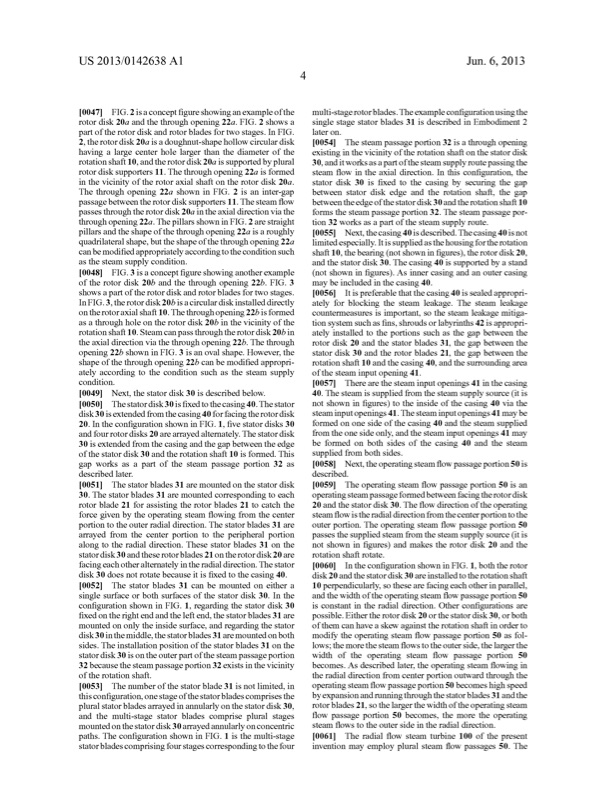
US 2013/0142638A1 Jun.6,2013 [0047] FIG.2isaconcept?gureshowinganexampleofthe multi-stagerotorblades.Theexamplecon?gurationusingthe rotor disk 20a and the through opening 22a. FIG. 2 shoWs a part of the rotor disk and rotor blades for tWo stages. In FIG. 2,therotordisk20aisadoughnut-shapeholloWcirculardisk having a large center hole larger than the diameter of the rotationshaft10,andtherotordisk20aissupportedbyplural 30,anditWorksasapartofthesteamsupplyroutepassingthe rotor disk supporters 11. The through opening 22a is formed in the vicinity of the rotor axial shaft on the rotor disk 20a. The through opening 22a shoWn in FIG. 2 is an inter-gap passagebetWeentherotordisksupporters11.The steam?oW passesthroughtherotordisk20a intheaxialdirectionviathe throughopening22a.ThepillarsshoWninFIG.2arestraight pillarsandtheshapeofthethroughopening22aisaroughly quadrilateralshape,buttheshapeofthethroughopening22a limitedespecially.Itissuppliedasthehousingfortherotation canbemodi?edappropriatelyaccordingtotheconditionsuch shaft10,thebearing(notshoWnin?gures),therotordisk20, as the steam supply condition. and the stator disk 30. The casing 40 is supported by a stand [0048] FIG.3isaconcept?gureshoWinganotherexample (notshoWnin?gures).Asinnercasingandanoutercasing of the rotor disk 20b and the through opening 22b. FIG. 3 shoWs a part of the rotor disk and rotor blades for tWo stages. InFIG.3,therotordisk20bisacirculardiskinstalleddirectly ontherotoraxialshaft10.Thethroughopening22bisformed as a through hole on the rotor disk 20b in the vicinity of the rotationshaft10.Steamcanpassthroughtherotordisk20bin theaxialdirectionviathethroughopening22b.Thethrough opening 22b shoWn inFIG. 3 isan oval shape. However, the shapeofthethroughopening22bcanbemodi?edappropri ately according to the condition such as the steam supply condition. may beincludedinthecasing40. [0056] Itispreferablethatthecasing40issealedappropri ately for blocking the steam leakage. The steam leakage countermeasures is important, so the steam leakage mitiga tionsystemsuchas?ns,shroudsorlabyrinths42isappropri ately installed to the portions such as the gap betWeen the rotor disk 20 and the stator blades 31, the gap betWeen the stator disk 30 and the rotor blades 21, the gap betWeen the rotation shaft 10 and the casing 40, and the surrounding area ofthesteaminputopening41. [0057] Therearethesteaminputopenings41inthecasing 40.Thesteamissuppliedfromthesteamsupplysource(itis [0049] Next,thestatordisk30isdescribedbeloW. [0050] Thestatordisk30is?xedtothecasing40.Thestator notshoWnin?gures)totheinsideofthecasing40viathe disk30isextendedfromthecasing40forfacingtherotordisk steaminputopenings41.Thesteaminputopenings41maybe 20. In the con?guration shoWn in FIG. 1, ?ve stator disks 30 and four rotor disks 20 are arrayed altemately. The stator disk 30 is extended from the casing and the gap betWeen the edge of the stator disk 30 and the rotation shaft 10 is formed. This gap Works as a part of the steam passage portion 32 as describedlater. formed on one side of the casing 40 and the steam supplied from the one side only, and the steam input openings 41 may be formed on both sides of the casing 40 and the steam suppliedfrombothsides. [0058] Next,theoperatingsteam?oWpassageportion50is described. [0051] Thestatorblades31aremountedonthestatordisk [0059] Theoperatingsteam?oWpassageportion50isan 30. The stator blades 31 are mounted corresponding to each rotor blade 21 for assisting the rotor blades 21 to catch the force given by the operating steam ?oWing from the center portion to the outer radial direction. The stator blades 31 are arrayed from the center portion to the peripheral portion along to the radial direction. These stator blades 31 on the statordisk30 and theserotorblades 21 on therotordisk20 are facingeachotheralternatelyintheradialdirection.Thestator [0060] Inthecon?gurationshoWninFIG.1,boththerotor disk 30 does not rotate because it is ?xed to the casing 40. disk 20 and the stator disk 30 are installed to the rotation shaft [0052] Thestatorblades31canbemountedoneithera 10perpendicularly,sothesearefacingeachotherinparallel, single surface or both surfaces of the stator disk 30. In the con?guration shoWn in FIG. 1, regarding the stator disk 30 ?xed on the right end and the left end, the stator blades 31 are mounted on only the inside surface, and regarding the stator disk30 inthemiddle, the statorblades 31 aremounted on both sides. The installation position of the stator blades 31 on the statordisk30 isontheouterpartofthesteampassageportion 32becausethesteampassageportion32existsinthevicinity oftherotationshaft. [0053] Thenumberofthestatorblade31isnotlimited,in operatingsteam?oWpassageportion50becomeshighspeed thiscon?guration,onestageofthestatorbladescomprisesthe byexpansionandrunningthroughthestatorblades31andthe pluralstatorbladesarrayedinannularlyonthestatordisk30, rotorblades21,sothelargertheWidthoftheoperatingsteam and the multi-stage stator blades comprise plural stages ?oW passage portion 50 becomes, the more the operating steam ?oWs to the outer side in the radial direction. paths.Thecon?gurationshoWninFIG.1isthemulti-stage [0061] Theradial?oWsteamturbine100ofthepresent statorbladescomprisingfourstagescorrespondingtothefour invention may employ plural steam ?oW passages 50. The mountedonthestatordisk30arrayedannularlyonconcentric single stage stator blades 31 is described in Embodiment 2 later on. [0054] Thesteampassageportion32isathroughopening existing in the vicinity of the rotation shaft on the stator disk steamHow intheaxialdirection.Inthiscon?guration,the stator disk 30 is ?xed to the casing by securing the gap betWeen stator disk edge and the rotation shaft, the gap betWeentheedgeofthestatordisk30andtherotationshaft10 forms the steam passage portion 32. The steam passage por tion 32 Works as a part of the steam supply route. [0055] Next,thecasing40isdescribed.Thecasing40isnot operatingsteampassageformedbetWeenfacingtherotordisk 20andthestatordisk30.TheHow directionoftheoperating steam How istheradialdirectionfrom thecenterportiontothe outer portion. The operating steam ?oW passage portion 50 passesthesuppliedsteamfromthesteamsupplysource(itis not shoWn in ?gures) and makes the rotor disk 20 and the rotation shaft rotate. andtheWidthoftheoperatingsteam?oW passageportion50 is constant in the radial direction. Other con?gurations are possible. Either the rotor disk 20 or the stator disk 30, or both of them can have a skeW against the rotation shaft in order to modify the operating steam ?oW passage portion 50 as fol loWs; the more the steam ?oWs to the outer side, the largerthe Width of the operating steam ?oW passage portion 50 becomes. As described later,the operating steam ?oWing in theradialdirectionfromcenterportionoutWardthroughthePDF Image | RADIAL FLOW STEAM TURBINE
PDF Search Title:
RADIAL FLOW STEAM TURBINEOriginal File Name Searched:
US20130142638.pdfDIY PDF Search: Google It | Yahoo | Bing
NFT (Non Fungible Token): Buy our tech, design, development or system NFT and become part of our tech NFT network... More Info
IT XR Project Redstone NFT Available for Sale: NFT for high tech turbine design with one part 3D printed counter-rotating energy turbine. Be part of the future with this NFT. Can be bought and sold but only one design NFT exists. Royalties go to the developer (Infinity) to keep enhancing design and applications... More Info
Infinity Turbine IT XR Project Redstone Design: NFT for sale... NFT for high tech turbine design with one part 3D printed counter-rotating energy turbine. Includes all rights to this turbine design, including license for Fluid Handling Block I and II for the turbine assembly and housing. The NFT includes the blueprints (cad/cam), revenue streams, and all future development of the IT XR Project Redstone... More Info
Infinity Turbine ROT Radial Outflow Turbine 24 Design and Worldwide Rights: NFT for sale... NFT for the ROT 24 energy turbine. Be part of the future with this NFT. This design can be bought and sold but only one design NFT exists. You may manufacture the unit, or get the revenues from its sale from Infinity Turbine. Royalties go to the developer (Infinity) to keep enhancing design and applications... More Info
Infinity Supercritical CO2 10 Liter Extractor Design and Worldwide Rights: The Infinity Supercritical 10L CO2 extractor is for botanical oil extraction, which is rich in terpenes and can produce shelf ready full spectrum oil. With over 5 years of development, this industry leader mature extractor machine has been sold since 2015 and is part of many profitable businesses. The process can also be used for electrowinning, e-waste recycling, and lithium battery recycling, gold mining electronic wastes, precious metals. CO2 can also be used in a reverse fuel cell with nafion to make a gas-to-liquids fuel, such as methanol, ethanol and butanol or ethylene. Supercritical CO2 has also been used for treating nafion to make it more effective catalyst. This NFT is for the purchase of worldwide rights which includes the design. More Info
NFT (Non Fungible Token): Buy our tech, design, development or system NFT and become part of our tech NFT network... More Info
Infinity Turbine Products: Special for this month, any plans are $10,000 for complete Cad/Cam blueprints. License is for one build. Try before you buy a production license. May pay by Bitcoin or other Crypto. Products Page... More Info
| CONTACT TEL: 608-238-6001 Email: greg@infinityturbine.com | RSS | AMP |