PDF Publication Title:
Text from PDF Page: 013
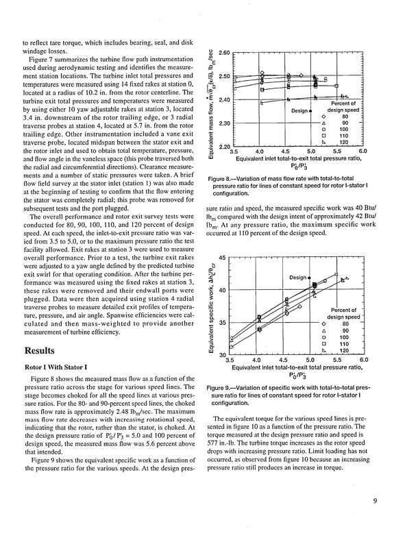
to reflect tare torque, which includes bearing, seal, and disk windage losses, Figure 7 summarizes the turbine flow path instrumentation used during aerodynamic testing and identifies the measure- ment station locations. The turbine inlet total pressures and traverse probes at station 4, located at 5.7 in. from the rotor =_ 2.30 _ trailing edge. Other instrumentation included a vane exit _- traverse probe, located midspan between the stator exit and "_ > 2.20 ......... the rotor inlet and used to obtain total temperature, pressure, "5 O" tleomcaptedratuartesarawdeiuresmoefas1u0r.e2dinu.sfirnogm1t4hfeixreodtorakcesnteartlisntea.tionTh0e, turbine exit total pressures and temperatures were measured byusingeither10yawadjustablerakesatstation3,located _ - _ 1., u Percenotf - 3.4 in. downstream of the rotor trailing edge, or 3 radial _ = Designq and flow angle in the vaneless space (this probe traversed both the radial and circumferential directions). Clearance measure- ments and a number of static pressures were taken. A brief flow field survey at the starer inlet (station 1) was also made at the beginning of testing to confirm that the flow entering the stator was completely radial; this probe was removed for subsequent tests and the port plugged, The overall performance and rotor exit survey tests were conducted for 80, 90, 100, 110, and 120 percent of design speed. At each speed, the inlet-to-exit pressure ratio was var- ied from 3.5 to 5.0, or to the maximum pressure ratio the test facility allowed. Exit rakes at station 3 were used to measure overall performance. Prior to a test, the turbine exit rakes were adjusted to a yaw angle defined by the predicted turbine ¢_ exit swirl for that operating condition. After the turbine per- -'- P_/P_ .t: formance was measured using the fixed rakes at station 3, "1 j._ Designq - these rakes were removed and their endwall ports were plugged. Data were then acquired using station 4 radial traverse probes to measure detailed exit profiles of tempera- ture, pressure, and air angle. Spanwise efficiencies were cal- _o40 _ _ _: "_ O of culated and then mass-weighted measurement of turbine efficiency. Results to provide another E >_ "_ _ ,,, _j _ Rotor I With Stator I Figure 8 shows the measured mass flow as a function of the pressure ratio across the stage for various speed lines. The stage becomes choked for all the speed lines at various pres- sure ratios. For the 80- and 90-percent speedlines, the choked mass flow rate is approximately 2.48 lbm/sec. The maximum mass flow rate decreases with increasing rotational speed, indicating that the rotor, rather than the stator, is choked. At the design pressure ratio of Pd/P_ = 5.0 and 100 percent of design speed, the measured mass flow was 5.6 percent above that intended, Figure 9 shows the equivalent specific work as a function of the pressure ratio for the various speeds. At the design pres- P()/P3 Figure 9._Variation of specific work with total-to-total pres- sure ratio for lines of constant speed for rotor I-stator I configuration. The equivalent torque for the various speed lines is pre- sented in figure I0 as a function of the pressure ratio. The torque measured at the design pressure ratio and speed is 577 in.-lb. The turbine torque increases as the rotor speed drops with increasing pressure ratio. Limit loading has not occurred, as observed from figure 10 because an increasing pressure ratio still produces an increase in torque. o• 2.60 ..................... _E - designspeed 0 80 -Q _ 2.60 _ _ _t, oE 2.40 -__2_L _ -k_ tu - o 100 [] 110 4.0 tx 120 5.5 6.0 3.5 Equivalent inlet total-to-exit total pressure ratio, 4.5 5.0 Figure 8.--Variation of mass flow rate with total-to-total pressure ratio for lines of constant speed for rotor I-stator I configuration. sure ratio and speed, the measured specific work was 40 Btu/ lb m compared with the design intent of approximately 42 Btu/ Ibm. At any pressure ratio, the maximum specific work occurred at 110 percent of the design speed. 45 ..................... n ¢n35 / • designspeed- O80- o 100 3.5 Equivalent inlet total-to-exit total pressure ratio, 4.0 4.5 5.0 5.5 6.0 __13 zx 90 [] 110 A 90 " _20 _PDF Image | Aerodynamic Radial Inflow Turbine Rotors
PDF Search Title:
Aerodynamic Radial Inflow Turbine RotorsOriginal File Name Searched:
19960003236.pdfDIY PDF Search: Google It | Yahoo | Bing
NFT (Non Fungible Token): Buy our tech, design, development or system NFT and become part of our tech NFT network... More Info
IT XR Project Redstone NFT Available for Sale: NFT for high tech turbine design with one part 3D printed counter-rotating energy turbine. Be part of the future with this NFT. Can be bought and sold but only one design NFT exists. Royalties go to the developer (Infinity) to keep enhancing design and applications... More Info
Infinity Turbine IT XR Project Redstone Design: NFT for sale... NFT for high tech turbine design with one part 3D printed counter-rotating energy turbine. Includes all rights to this turbine design, including license for Fluid Handling Block I and II for the turbine assembly and housing. The NFT includes the blueprints (cad/cam), revenue streams, and all future development of the IT XR Project Redstone... More Info
Infinity Turbine ROT Radial Outflow Turbine 24 Design and Worldwide Rights: NFT for sale... NFT for the ROT 24 energy turbine. Be part of the future with this NFT. This design can be bought and sold but only one design NFT exists. You may manufacture the unit, or get the revenues from its sale from Infinity Turbine. Royalties go to the developer (Infinity) to keep enhancing design and applications... More Info
Infinity Supercritical CO2 10 Liter Extractor Design and Worldwide Rights: The Infinity Supercritical 10L CO2 extractor is for botanical oil extraction, which is rich in terpenes and can produce shelf ready full spectrum oil. With over 5 years of development, this industry leader mature extractor machine has been sold since 2015 and is part of many profitable businesses. The process can also be used for electrowinning, e-waste recycling, and lithium battery recycling, gold mining electronic wastes, precious metals. CO2 can also be used in a reverse fuel cell with nafion to make a gas-to-liquids fuel, such as methanol, ethanol and butanol or ethylene. Supercritical CO2 has also been used for treating nafion to make it more effective catalyst. This NFT is for the purchase of worldwide rights which includes the design. More Info
NFT (Non Fungible Token): Buy our tech, design, development or system NFT and become part of our tech NFT network... More Info
Infinity Turbine Products: Special for this month, any plans are $10,000 for complete Cad/Cam blueprints. License is for one build. Try before you buy a production license. May pay by Bitcoin or other Crypto. Products Page... More Info
| CONTACT TEL: 608-238-6001 Email: greg@infinityturbine.com | RSS | AMP |