PDF Publication Title:
Text from PDF Page: 002
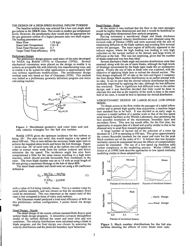
THE DESIGN OF A HIGH-SPEED RADIAL INFLOW TURBINE The baseline turbine duty was selected for a low cost single shaft gas turbine in the 200kW class. This results in modest gas temperature levels. However, the aerodynamic duty would also be appropriate for the gas generator turbine of a higher pressure ratio two shaft engine. Detail Design - Rotor At the outset it was realised that the flow in the rotor passages would be highly three dimensional and that it would be beneficial to design using three dimensional flow analysis programs. Having estimated a meridional shape and blade thickness distribution, computed velocity distributions were obtained using the inviscid code of Denton (1983) and were assessed with the aim of minimising diffusion on the blade surfaces and avoiding flow reversal within the passages. The main region of difficulty appeared in the inducer region, where the high loading was leading to very high velocities on the suction surface at the shroud, and large levels of diffusion at the hub. This was not surprising, given that the number of blades employed was less than ideal. Several alternative blade angle and annulus distributions were then assessed, along with the use of more blades, although the high levels of blockage necessitated by the blade taper made this an unattractive option. Finally the use of rake at blade inlet was explored, with the objective of applying blade lean to unload the shroud section. The final design employed 20' of rake at the inlet and figure 2 compares the final design Mach number distributions to an earlier attempt with no rake. It can be seen that the shroud velocity distribution has been markedly improved by applying the rake, although the hub diffusion has worsened. There is significant hub diffusion even in the earlier design, and it was therefore decided that little could be done to alleviate this and that as the majority of the work is done in the outer half of the rotor, it would be best to optimise the shroud distribution. To obtain access to the flow within the passages of a radial inflow turbine and to permit high quality data acquisition, a machine larger than standard has to be built. It was decided at an early stage to construct a model turbine of a similar scale to that of the low-speed axial research facilities at the Whittle Laboratory, thus permitting the best possible resolution of the mainstream, boundary layer and secondary flows. This new rig would offer, for the first time, the opportunity to acquire data of a detail and quality similar to that so far obtained only in axial flow research programmes. A large number of factors led to the selection of a rotor tip diameter of 1.219 m operating at 450 rpm. This gives approximately the correct Reynolds numbers for the stator and rotor but the peak Mach numbers are of the order of 0.1. It follows that true dynamic similarity cannot be maintained because the effects of compressibility cannot be simulated. The use of a low-speed rig therefore adds further complexity to the modelling process. Wisler (1984) and Joslyn et al (1990) both describe approaches to low-speed similarity modelling similar to those adopted here. The leading parameters are: Mass Flow 1.58 kg/s 1161 K 4.7 Stator Inlet Temperature Total-Total Pressure ratio Target Total-Total efficiency 87% Preliminary Design The preliminary design process used many of the rules developed by NASA (eg Rohlik (1975) or Glassman (1976)). Several mechanical constraints were placed on the design to enable it to achieve an acceptable life with relatively low manufacturing costs, and to enable it to be scaled for other applications to approximately half size without significant modifications. The aerodynamic design method used was based on that of Glassman (1976). This method was linked to a preliminary geometry definition program and stress calculating routines. 1 72' M2=0.39 18.4' M1m1= 0.32 M2re1=0.83^. 66' M 1=0.84 Figure 1: Meridional geometry and rotor inlet and exit rms velocity triangles for the full size turbine Rohlik (1975) gives the optimum incidence for this turbine as being -26'. For zero exit swirl, this would require a tip speed of about 650 m/s. This in turn defines the necessary blade taper ratio to achieve the required stress levels and hence the hub blockage. Figure 1 shows that -26' of swirl were left at the turbine rms exit radius in order to extract more work from the turbine exducer and hence minimise the tip speed. The incidence angle has also been compromised a little for the same reason resulting in a high rotor reaction, which should provide favourable flow conditions in the rotor. The rotor blade number was set to 14 with an axial length of 64 mm giving a maximum blockage at the hub of about 60%. The stator blade number and chord were set using a lift coefficient defined as Shroud Mean CL=thi VØ1 — rhr2V02( r2 Z f (P01 — P2)rbdr rl 1 ) 16 0.8 0.0 Fraction of meridional distance with a value of 0.6 being initially chosen. This is a modest value by axial turbine standards, and was chosen so that the secondary flows could be minimised. This was important as the aspect ratio of this vaneislowcomparedtothoseofmanyaxialturbines. The Glassman model predicted a total-total efficiency of 84% for this preliminary turbine configuration, 3 points below the design target. Detail Design - Nozzle The detail design of the nozzle utilised standard Rolls Royce axial turbine blade design programs. A streamline curvature throughflow model of the turbine defined the stator and rotor inlet and exit conditions. The velocity distributions were calculated using a blade to blade program, and the final design was chosen by assessing the velocity distributions and the predicted boundary layer behaviour. 1.6 0.8 0.0 Hub Fraction of meridional distance • Early Design -Final Design AERODYNAMIC DESIGN OF LARGE-SCALE LOW-SPEED MODEL 0.0 0.5 1.0 Fraction of meridional distance Figure 2: Mach number distributions for the full size turbine showing the effects of rotor blade inlet rake Downloaded from http://asmedigitalcollection.asme.org/GT/proceedings-pdf/GT1991/78989/V001T01A077/2400491/v001t01a077-91-gt-220.pdf by guest on 23 January 2021PDF Image | Design and Testing of a Radial Flow Turbine for Aerodynamic Research
PDF Search Title:
Design and Testing of a Radial Flow Turbine for Aerodynamic ResearchOriginal File Name Searched:
v001t01a077-91-gt-220.pdfDIY PDF Search: Google It | Yahoo | Bing
NFT (Non Fungible Token): Buy our tech, design, development or system NFT and become part of our tech NFT network... More Info
IT XR Project Redstone NFT Available for Sale: NFT for high tech turbine design with one part 3D printed counter-rotating energy turbine. Be part of the future with this NFT. Can be bought and sold but only one design NFT exists. Royalties go to the developer (Infinity) to keep enhancing design and applications... More Info
Infinity Turbine IT XR Project Redstone Design: NFT for sale... NFT for high tech turbine design with one part 3D printed counter-rotating energy turbine. Includes all rights to this turbine design, including license for Fluid Handling Block I and II for the turbine assembly and housing. The NFT includes the blueprints (cad/cam), revenue streams, and all future development of the IT XR Project Redstone... More Info
Infinity Turbine ROT Radial Outflow Turbine 24 Design and Worldwide Rights: NFT for sale... NFT for the ROT 24 energy turbine. Be part of the future with this NFT. This design can be bought and sold but only one design NFT exists. You may manufacture the unit, or get the revenues from its sale from Infinity Turbine. Royalties go to the developer (Infinity) to keep enhancing design and applications... More Info
Infinity Supercritical CO2 10 Liter Extractor Design and Worldwide Rights: The Infinity Supercritical 10L CO2 extractor is for botanical oil extraction, which is rich in terpenes and can produce shelf ready full spectrum oil. With over 5 years of development, this industry leader mature extractor machine has been sold since 2015 and is part of many profitable businesses. The process can also be used for electrowinning, e-waste recycling, and lithium battery recycling, gold mining electronic wastes, precious metals. CO2 can also be used in a reverse fuel cell with nafion to make a gas-to-liquids fuel, such as methanol, ethanol and butanol or ethylene. Supercritical CO2 has also been used for treating nafion to make it more effective catalyst. This NFT is for the purchase of worldwide rights which includes the design. More Info
NFT (Non Fungible Token): Buy our tech, design, development or system NFT and become part of our tech NFT network... More Info
Infinity Turbine Products: Special for this month, any plans are $10,000 for complete Cad/Cam blueprints. License is for one build. Try before you buy a production license. May pay by Bitcoin or other Crypto. Products Page... More Info
| CONTACT TEL: 608-238-6001 Email: greg@infinityturbine.com | RSS | AMP |