PDF Publication Title:
Text from PDF Page: 005
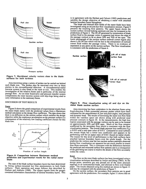
i:;:= jtflj Suction surface Full size t Pressure surface Model off of blade ace fluid Pfof endwall fluid Figure 7: Meridional velocity vectors close to the blade surfaces for both turbines Area traversing using a variety of probes can be carried out behind each blade row. The probes may be traversed over two or three pitches in the circumferential direction. A circumferential-radial traverse system is also fitted to the rotor at exit. This enables the investigation of the relative frame and in particular, of the internal passage flow. An on-rotor Scanivalve and pressure transfer system complements the rotor traverse system with slip-rings being used to carry information to the stationary frame. DISCUSSION OF TEST RESULTS Stator Figure 8 shows the good comparison of experimental results from the stator blade statics with the predicted values from a Martensen method calculation at the design flow coefficient. The data shows that there is no diffusion on the suction surface which satisfies the design objective while the continuous acceleration on the pressure surface is a consequence of the relatively low loading coefficient chosen for this blade row. Suction surface Endwall V Vin Prediction Experiment 0.5 1.0 Fraction of surface length Figure 9: Flow visualisation using oil and dye on the stator blade suction surface Area traversing has been undertaken in the absolute frame using fixed-direction 5-hole pyramidal pressure probes which have been calibrated for the measurement of yaw and pitch angles, total pressure and dynamic head. The results of traversing the stator exit flow field within the vaneless space are shown along with predicted total pressure contours in figure 10. In the measurements, the high loss regions associated with the passage vortices can be seen to be centred on approximately 20% and 80% span. Much of the flow remains unaffected by the secondary flow which is consistent with the flow visualisation patterns. The overall blade pressure loss coefficient (Y p) is 0.033 with a mid span value of 0.012. Compared to axial turbines the nozzle blade has a lower loss coefficient and appears to be performing well for an aspect ratio of 0.821 (based on radial chord). The reason for this level of performance is that both surfaces have attached laminar boundary layers over the whole length. For the prediction the vortices near the two suction surface endwalls observed during flow visualisation are apparent but are much smaller in extent than those measured. This is consistent with the differences between the predicted and measured surface flow patterns and is a consequence of the grid being too coarse to resolve the details of the flow accurately within the vortex. Rotor The flow on the rotor blade surfaces has been investigated using a visualisation technique described by Joslyn and Dring (1983). At the design point, ammonia gas was passed out of the static pressure tappings in an instrumented blade, and allowed to flow over Ozalid paper. The results obtained using this method are shown in figure 11 and may be compared with the predictions of figure 7. On the suction surface, the secondary flow patterns are in good agreement with the predictions. For example, figure 11 shows that on 0. 1 0.0 Figure 8: Comparison between Martensen method prediction and experimental results for the radial stator blade The state of the blade surface boundary layers has been determined by fitting surface-mounted hot film anemometers to both blade surfaces. Their operation and usage follows that described by Hodson and Addison (1988). The output signals from the gauges contained information characteristic of laminar boundary layers. This Model is in agreement with the Herbert and Calvert (1982) predictions and satisfies the design objective of obtaining a stator with attached laminar boundary layers throughout. The blade and endwall flow fields of the stator blade have been investigated using an oil and dye flow visualisation mixture. Figure 9 presents the resulting flow patterns. The upper figure shows the suction surface viewed looking upstream and may be compared to the predictions of figure 4. The lift off generated by entrainment of blade surface fluid to the passage vortex is apparent and shows the edge of the passage vortices to be at about 30% and 70% of the span. The lower photograph of the suction surface endwall comer region also shows a lift off line which will be due to the entrainment of endwall corner fluid within the passage vortex. There is no evidence of separation at any point on the suction surface. The flow visualisation is consistent with the predictions of figure 4. Downloaded from http://asmedigitalcollection.asme.org/GT/proceedings-pdf/GT1991/78989/V001T01A077/2400491/v001t01a077-91-gt-220.pdf by guest on 23 January 2021PDF Image | Design and Testing of a Radial Flow Turbine for Aerodynamic Research
PDF Search Title:
Design and Testing of a Radial Flow Turbine for Aerodynamic ResearchOriginal File Name Searched:
v001t01a077-91-gt-220.pdfDIY PDF Search: Google It | Yahoo | Bing
NFT (Non Fungible Token): Buy our tech, design, development or system NFT and become part of our tech NFT network... More Info
IT XR Project Redstone NFT Available for Sale: NFT for high tech turbine design with one part 3D printed counter-rotating energy turbine. Be part of the future with this NFT. Can be bought and sold but only one design NFT exists. Royalties go to the developer (Infinity) to keep enhancing design and applications... More Info
Infinity Turbine IT XR Project Redstone Design: NFT for sale... NFT for high tech turbine design with one part 3D printed counter-rotating energy turbine. Includes all rights to this turbine design, including license for Fluid Handling Block I and II for the turbine assembly and housing. The NFT includes the blueprints (cad/cam), revenue streams, and all future development of the IT XR Project Redstone... More Info
Infinity Turbine ROT Radial Outflow Turbine 24 Design and Worldwide Rights: NFT for sale... NFT for the ROT 24 energy turbine. Be part of the future with this NFT. This design can be bought and sold but only one design NFT exists. You may manufacture the unit, or get the revenues from its sale from Infinity Turbine. Royalties go to the developer (Infinity) to keep enhancing design and applications... More Info
Infinity Supercritical CO2 10 Liter Extractor Design and Worldwide Rights: The Infinity Supercritical 10L CO2 extractor is for botanical oil extraction, which is rich in terpenes and can produce shelf ready full spectrum oil. With over 5 years of development, this industry leader mature extractor machine has been sold since 2015 and is part of many profitable businesses. The process can also be used for electrowinning, e-waste recycling, and lithium battery recycling, gold mining electronic wastes, precious metals. CO2 can also be used in a reverse fuel cell with nafion to make a gas-to-liquids fuel, such as methanol, ethanol and butanol or ethylene. Supercritical CO2 has also been used for treating nafion to make it more effective catalyst. This NFT is for the purchase of worldwide rights which includes the design. More Info
NFT (Non Fungible Token): Buy our tech, design, development or system NFT and become part of our tech NFT network... More Info
Infinity Turbine Products: Special for this month, any plans are $10,000 for complete Cad/Cam blueprints. License is for one build. Try before you buy a production license. May pay by Bitcoin or other Crypto. Products Page... More Info
| CONTACT TEL: 608-238-6001 Email: greg@infinityturbine.com | RSS | AMP |