PDF Publication Title:
Text from PDF Page: 006
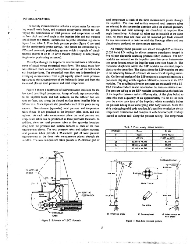
INSTRUMENTATION The facility instrumentation includes a torque meter for measur- ing overall work input, and standard aerodynamic probes for sur- veying the distributions of total pressure and temperature as well as flow pitch and swirl angle at the impeUer inlet and exit stations and diffuser exit station. Information on probe locations is given in figure 3 and table 3. Five- hole pressure probes (figure 4) are used for the aerodynamic probe surveys. The probes are controlled by a PC-based automatic positioning system which is capable of simul- taneous control of up to 16 drive motors (typically, 8 auto-yawing single-axis- positioning actuators). Mass fl9w through the impeller is determined from a calibration curve of actual versus theoretical mass flows. The actual mass flow was obtained from detailed aerodynamic surveys of the bellmouth exit boundary layer. The theoretical mass flow rate is determined by averaging measurements from eight equally spaced static pressure taps around the circumference of the bellmouth throat and from the measured plenum total pressure and total temperature. Figure 5 shows a schematic of instrumentation locations for the low speed centrifugal compressor. Arrays of static taps are provided on the impeller blade and hub surfaces, on the diffuser hub and vane surfaces, and along the shroud surface from impeller inlet to diffuser exit. Static taps are also provided at each of the probe survey stations. Five-element (spanwise) total pressure and temperature rakes (figure 6) are provided at the impeller inlet, knee, and exit regions. At each rake measurement plane the total pressure and temperature rakes can be positioned at three pitchwise locations. In addition,- there are total pressure tubes at five spanwise locations along both the pressure and suction surfaces at each of the rake measurement planes. The total pressure rakes and surface mounted total pressure tubes provide a 25-element grid of total pressure measurements at the three rake measurement planes through the impeller. The total temperature rakes provide a 15--element grid of total temperature at each of the three measurement planes through the impeller. The rake and surface mounted total pressure tubes are oriented in the streamwise direction using the channel geometry for guidance and their openings are chamfered to improve flow angle insensitivity. Although all rakes can be installed at the same time, no more than one rake will be installed per blade channel for any measurement in order to minimize blockage effects and any disturbances produced on downstream elements. All rotating frame pressures are sensed through 0.05 centimeter (0.020 inch) I.D. tubing by silicon pressure transducers houset in five 48-port electronic scanning pressure (ESP) modules. The ESP modules are mounted on the impeller centerline on an instrumenta- tion tower located under the impeller nose cone (see figure 3). The transducer diaphrams within the ESP modules are oriented perpen- dicular to the centerline. The signals from the ESP modules are sent to the laboratory frame of reference via an electrical slip ring assem- bly. On-line calibration of the ESP modules is accomplished using a pneumatic slip ring which supplies calibration pressures to the ESP modules. The supplied calibration pressures are measured with a SE- TRA transducer which is also mounted on the instrumentation tower. The pressure tubing to the ESP modules is routed down the backfacc of the impeller between radial stiffening ribs. A flat plate bolted to these ribs traps a quantity of air approximately 7.6 cm (3 in) thick over the entire back face of the impeller, which essentially bathes the pressure tubing in air undergoing solid body rotation. Since this air is undergoing solid body rotation, it's possible to calculate the air temperature distribution and compare it with thermocouple readings located at various radii along the pressure tubing. The temperature STA. 3 - TRAVERSING /T 2//2r 0.30 - - PROBES STA. / 1 TA. -FRONT 2a FLWFEEDTHROUGH ~3/4 \-TRANSDUCER TOWER figure 3 Schematic of LSCC flowpath. 00 VIEW VIEW b) Sening head 1.824 mm 9.552 mm 914.4m '! ,-ROTATING 5 STATION 0 1 2& 2b 3 50.8 mm 914.4 1mmn Table 3 Probe survey station locations. Z,cm R,cm a) Inlet hub probe ) Inlet shroud an exit probe l-20.373 f/ 73 32.205 to 46.543 32.205 to 46.543 32.205 to 46.543 1,90 to 43.511 13.905 to 43.511 81.20 95.872 167.640 THERMOCOUPLE- Figure 4 Fivc-hole pressure probes.PDF Image | NASA Low-Speed Centrifugal Compressor for 3-D Viscous Code
PDF Search Title:
NASA Low-Speed Centrifugal Compressor for 3-D Viscous CodeOriginal File Name Searched:
a242473.pdfDIY PDF Search: Google It | Yahoo | Bing
NFT (Non Fungible Token): Buy our tech, design, development or system NFT and become part of our tech NFT network... More Info
IT XR Project Redstone NFT Available for Sale: NFT for high tech turbine design with one part 3D printed counter-rotating energy turbine. Be part of the future with this NFT. Can be bought and sold but only one design NFT exists. Royalties go to the developer (Infinity) to keep enhancing design and applications... More Info
Infinity Turbine IT XR Project Redstone Design: NFT for sale... NFT for high tech turbine design with one part 3D printed counter-rotating energy turbine. Includes all rights to this turbine design, including license for Fluid Handling Block I and II for the turbine assembly and housing. The NFT includes the blueprints (cad/cam), revenue streams, and all future development of the IT XR Project Redstone... More Info
Infinity Turbine ROT Radial Outflow Turbine 24 Design and Worldwide Rights: NFT for sale... NFT for the ROT 24 energy turbine. Be part of the future with this NFT. This design can be bought and sold but only one design NFT exists. You may manufacture the unit, or get the revenues from its sale from Infinity Turbine. Royalties go to the developer (Infinity) to keep enhancing design and applications... More Info
Infinity Supercritical CO2 10 Liter Extractor Design and Worldwide Rights: The Infinity Supercritical 10L CO2 extractor is for botanical oil extraction, which is rich in terpenes and can produce shelf ready full spectrum oil. With over 5 years of development, this industry leader mature extractor machine has been sold since 2015 and is part of many profitable businesses. The process can also be used for electrowinning, e-waste recycling, and lithium battery recycling, gold mining electronic wastes, precious metals. CO2 can also be used in a reverse fuel cell with nafion to make a gas-to-liquids fuel, such as methanol, ethanol and butanol or ethylene. Supercritical CO2 has also been used for treating nafion to make it more effective catalyst. This NFT is for the purchase of worldwide rights which includes the design. More Info
NFT (Non Fungible Token): Buy our tech, design, development or system NFT and become part of our tech NFT network... More Info
Infinity Turbine Products: Special for this month, any plans are $10,000 for complete Cad/Cam blueprints. License is for one build. Try before you buy a production license. May pay by Bitcoin or other Crypto. Products Page... More Info
| CONTACT TEL: 608-238-6001 Email: greg@infinityturbine.com | RSS | AMP |