PDF Publication Title:
Text from PDF Page: 011
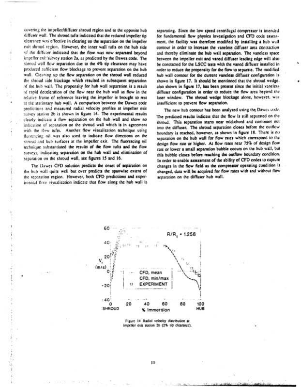
covering the inpcller/diffuser shroud region and to the opposite hub diffuser wall. The shroud tufts indicated that the reduced impeller tip clearance was effective in clearing up the separation on the impeller exi, shroud region. However, the inner wall tufts on the hub side ,of the diffus;.r indicated that the flow was now separated beyond impeller cxit-sUrvcy station 2a, as predicted by the Dawes code. The ,jhroud wall flow separation due to the 4% tip clearance may have produccd 5ufficicnt flow blockage to prevent separation on the hub wall. Clcaning up the flow separation on the shroud wall reduced the shroud ,iide blockage which resulted in subsequent separation of the hub wall, The propensity for hub wall separation is a result of rapid deceleration of the flow near the hub wall as flow in the relative frame of reference leaving the impeller is brought to rest at the stationary hub wall. A comparison between the Dawes code prediction3 and measured radial velocity profiles at impeller exit survey station 2b is shown in figure 14. The experimental results clcarly indiaatc a flow separation on the hub wall and show no i~mlicjion of separation on the shroud wall which is in agreement withi dfe flow tufts, Another flow visualization technique using luoru,;cing oil wahealso usd to indicate flow directions on the . ind hil wufaes als tusdto indlericate fldirection o thel shroud and hub surfaces at the impeller exit. The fluorescing oil technique substantiated the results of the flow tufts and the flow surveyi, indicating separation on the hub wall and elimination of separation tn the shroud wall, see figures 15 and 16. The Dawes CFD solution predicts the onset of separation on the hub wall quite well but over predicts the spanwise extent of the ieparation region. However, both CFD predictions and exper- iricnial flo.v visualization indicate that flow along the hub wall is 60 40 , Vr (mIs))' -20, 40' 0 - separating. Since the low speed centrifugal compressor is intended for fundamental flow physics Investigation and CFD code assess- ment, the facility was therefore modified by installing a hub wall contour in order to increase the vaneless diffuser area contractioo and thereby eliminate the hub wall separition. The vaneless space between the impeller exit and vaned diffuser leading edge will also be contracted for the LSCC tests with the vaned diffuser installed in order to reduce the propensity for the flow to separate. The modified hub wall contour for the current vaneless diffuser configuration is shown in figure 17. It should be mentioned that the shroud wedge. also shown in figure 17, has been present since the initial vancless diffuser configuration in order to reduce the flow area beyond the laser window. The shroud wedge blockage alone, however, was insufficient to prevent flow separation. The new hub contour has been analyzed using th. Dawes ;ode, The predicted results indicate that the flow is still separated on the shroud. This separation starts near mid-chord and continues out into the diffuser. The shroud separation closes before the outflow boundary is reached, however, as shown In figure 18. There is no separation on the hub wall for flow rates which correspond to the design flow rate or higher. At flow rates near 75% of design flow rate or lower a small separation bubble occurs on the hub wall, but this bubble closes before reaching the outflow boundary condition. In order to enable assessment of the ability of CFD codes to capture changes in the flow field as the compressor operating condition is changed, data will be acquired for flow rates with and without flow separation on the diffuser hub wall. R/R ,1.258 CFD, mean j CFD, min/max EXPERIMENT 0 20 40 60 80 100 SHROUD % Immersion HUB Figure 14 Radial velocity distribution at Impeller exit taton 2b (2%tip clearance). It)PDF Image | NASA Low-Speed Centrifugal Compressor for 3-D Viscous Code
PDF Search Title:
NASA Low-Speed Centrifugal Compressor for 3-D Viscous CodeOriginal File Name Searched:
a242473.pdfDIY PDF Search: Google It | Yahoo | Bing
NFT (Non Fungible Token): Buy our tech, design, development or system NFT and become part of our tech NFT network... More Info
IT XR Project Redstone NFT Available for Sale: NFT for high tech turbine design with one part 3D printed counter-rotating energy turbine. Be part of the future with this NFT. Can be bought and sold but only one design NFT exists. Royalties go to the developer (Infinity) to keep enhancing design and applications... More Info
Infinity Turbine IT XR Project Redstone Design: NFT for sale... NFT for high tech turbine design with one part 3D printed counter-rotating energy turbine. Includes all rights to this turbine design, including license for Fluid Handling Block I and II for the turbine assembly and housing. The NFT includes the blueprints (cad/cam), revenue streams, and all future development of the IT XR Project Redstone... More Info
Infinity Turbine ROT Radial Outflow Turbine 24 Design and Worldwide Rights: NFT for sale... NFT for the ROT 24 energy turbine. Be part of the future with this NFT. This design can be bought and sold but only one design NFT exists. You may manufacture the unit, or get the revenues from its sale from Infinity Turbine. Royalties go to the developer (Infinity) to keep enhancing design and applications... More Info
Infinity Supercritical CO2 10 Liter Extractor Design and Worldwide Rights: The Infinity Supercritical 10L CO2 extractor is for botanical oil extraction, which is rich in terpenes and can produce shelf ready full spectrum oil. With over 5 years of development, this industry leader mature extractor machine has been sold since 2015 and is part of many profitable businesses. The process can also be used for electrowinning, e-waste recycling, and lithium battery recycling, gold mining electronic wastes, precious metals. CO2 can also be used in a reverse fuel cell with nafion to make a gas-to-liquids fuel, such as methanol, ethanol and butanol or ethylene. Supercritical CO2 has also been used for treating nafion to make it more effective catalyst. This NFT is for the purchase of worldwide rights which includes the design. More Info
NFT (Non Fungible Token): Buy our tech, design, development or system NFT and become part of our tech NFT network... More Info
Infinity Turbine Products: Special for this month, any plans are $10,000 for complete Cad/Cam blueprints. License is for one build. Try before you buy a production license. May pay by Bitcoin or other Crypto. Products Page... More Info
| CONTACT TEL: 608-238-6001 Email: greg@infinityturbine.com | RSS | AMP |