PDF Publication Title:
Text from PDF Page: 013
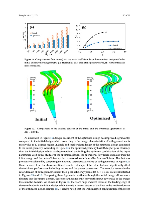
Energies 2019, 12, x FOR PEER REVIEW 13 of 22 Energies 2019, 12, x FOR PEER REVIEW 13 of 22 both geometries = 1400 Pa, in Figure 13, clearly illustrates the lower air velocity at the mid-chord both geometries = 1400 Pa, in Figure 13, clearly illustrates the lower air velocity at the mid-chord Energies 2019, 12, 2791 of the optimised design. 13 of 22 of the optimised design. 6 6 5 4 3 2 1 0 5 (a) 4 3 2 1 (a) Initial Initial Optimized 0 Optimized 0 [Pa] 0 [Pa] 12 12 1 10 8 6 4 2 0 4 3.0 4.0 0 (b) 8 6 4 2 0 Initial (b) 0.0 1.0 Optimized 0.0 1.0 2.0 φ φ 2.0 3.0 Initial Optimized Figure 12. Comparison of flow rate (a) and the input coefficient (b) of the optimised design with the Figure 12. Comparison of flow rate (a) and the input coefficient (b) of the optimised design with the Figure 12. Comparison of flow rate (a) and the input coefficient (b) of the optimised design with the initial outflow turbine geometry. ((a) Horizontal axis: total-static pressure drop, (b) Horizontal axis: initial outflow turbine geometry. ((a) Horizontal axis: total-static pressure drop, (b) Horizontal axis: initial outflow turbine geometry. ((a) Horizontal axis: total-static pressure drop, (b) Horizontal axis: flowflocwoecffioecfifeincite).nt). flow coefficient). .0 Figure 13. Comparison of the velocity contour of the initial and the optimised geometries at Figure 13. Comparison of the velocity contour of the initial and the optimised geometries at = ∆P =1400Pa. Figure 13. Comparison of the velocity contour of the initial and the optimised geometries at = 1400 Pa. 0 1400 Pa. As illustrated in Figure 14a, torque coefficient of the optimised design has improved significantly As illustrated in Figure 14a, torque coefficient of the optimised design has improved compared to the initial design, which according to the design characteristics of both geometries, is As illustrated in Figure 14a, torque coefficient of the optimised design has improved significantly compared to the initial design, which according to the design characteristics of both mostly due to 10 degrees higher LE angle and smaller chord length of the optimised design compared significantly compared to the initial design, which according to the design characteristics of both geometries, is mostly due to 10 degrees higher LE angle and smaller chord length of the optimised to the initial geometry. According to Figure 14b, the optimised geometry has 30% higher peak efficiency geometries, is mostly due to 10 degrees higher LE angle and smaller chord length of the optimised design compared to the initial geometry. According to Figure 14b, the optimised geometry has 30% than the initial design, which has been obtained by finding the optimum combination of the input design compared to the initial geometry. According to Figure 14b, the optimised geometry has 30% higher peak efficiency than the initial design, which has been obtained by finding the optimum parameters used in this study. For the optimised design, the operational flow range is smaller than the higher peak efficiency than the initial design, which has been obtained by finding the optimum combination of the input parameters used in this study. For the optimised design, the operational initial design and the peak efficiency point has moved towards smaller flow coefficients. This fact was combination of the input parameters used in this study. For the optimised design, the operational flow range is smaller than the initial design and the peak efficiency point has moved towards smaller previously explained by comparing the flowrate versus pressure drop of both geometries in Figure 12a. flow range is smaller than the initial design and the peak efficiency point has moved towards smaller flow coefficients. This fact was previously explained by comparing the flowrate versus pressure drop It can be noted from the above-mentioned results that shape of the rotor blade can significantly affect flow coefficients. This fact was previously explained by comparing the flowrate versus pressure drop of both geometries in Figure 12a. It can be noted from the above-mentioned results that shape of the the turbine’s performance including torque and the power conversion. The velocity vectors in the of both geometries in Figure 12a. It can be noted from the above-mentioned results that shape of the rotor blade can significantly affect the turbine’s performance including torque and the power rotor domain of both geometries near their peak efficiency points (at ∆P0 = 1400 Pa) are illustrated rotor blade can significantly affect the turbine’s performance including torque and the power conversion. The velocity vectors in the rotor domain of both geometries near their peak efficiency in Figures 15 and 16. Comparing these figures shows that although the initial design allows more conversion. The velocity vectors in the rotor domain of both geometries near their peak efficiency points (at = 1400 Pa) are illustrated in Figures 15 and 16. Comparing these figures shows that flowrate into theturbine domain, the rotor cannot efficiently convert the input power due to the energy points (at = 1400 Pa) are illustrated in Figures 15 and 16. Comparing these figures shows that although the initial design allows more flowrate into the turbine domain, the rotor cannot efficiently losses in the domain. As shown in Figure 15, there are huge incident losses at the leading-edge of although the initial design allows more flowrate into the turbine domain, the rotor cannot efficiently convert the input power due to the energy losses in the domain. As shown in Figure 15, there are the rotor blades in the initial design while there is a perfect stream of the flow in the turbine domain convert the input power due to the energy losses in the domain. As shown in Figure 15, there are huge incident losses at the leading-edge of the rotor blades in the initial design while there is a perfect of the optimised design (Figure 16). It can be noted that the well-matched configuration of the rotor huge incident losses at the leading-edge of the rotor blades in the initial design while there is a perfect Q [m^3/s] Q [m^3/s] CA CAPDF Image | Unidirectional Radial-Air-Turbine OWC Wave Energy Converters
PDF Search Title:
Unidirectional Radial-Air-Turbine OWC Wave Energy ConvertersOriginal File Name Searched:
energies-12-02791.pdfDIY PDF Search: Google It | Yahoo | Bing
NFT (Non Fungible Token): Buy our tech, design, development or system NFT and become part of our tech NFT network... More Info
IT XR Project Redstone NFT Available for Sale: NFT for high tech turbine design with one part 3D printed counter-rotating energy turbine. Be part of the future with this NFT. Can be bought and sold but only one design NFT exists. Royalties go to the developer (Infinity) to keep enhancing design and applications... More Info
Infinity Turbine IT XR Project Redstone Design: NFT for sale... NFT for high tech turbine design with one part 3D printed counter-rotating energy turbine. Includes all rights to this turbine design, including license for Fluid Handling Block I and II for the turbine assembly and housing. The NFT includes the blueprints (cad/cam), revenue streams, and all future development of the IT XR Project Redstone... More Info
Infinity Turbine ROT Radial Outflow Turbine 24 Design and Worldwide Rights: NFT for sale... NFT for the ROT 24 energy turbine. Be part of the future with this NFT. This design can be bought and sold but only one design NFT exists. You may manufacture the unit, or get the revenues from its sale from Infinity Turbine. Royalties go to the developer (Infinity) to keep enhancing design and applications... More Info
Infinity Supercritical CO2 10 Liter Extractor Design and Worldwide Rights: The Infinity Supercritical 10L CO2 extractor is for botanical oil extraction, which is rich in terpenes and can produce shelf ready full spectrum oil. With over 5 years of development, this industry leader mature extractor machine has been sold since 2015 and is part of many profitable businesses. The process can also be used for electrowinning, e-waste recycling, and lithium battery recycling, gold mining electronic wastes, precious metals. CO2 can also be used in a reverse fuel cell with nafion to make a gas-to-liquids fuel, such as methanol, ethanol and butanol or ethylene. Supercritical CO2 has also been used for treating nafion to make it more effective catalyst. This NFT is for the purchase of worldwide rights which includes the design. More Info
NFT (Non Fungible Token): Buy our tech, design, development or system NFT and become part of our tech NFT network... More Info
Infinity Turbine Products: Special for this month, any plans are $10,000 for complete Cad/Cam blueprints. License is for one build. Try before you buy a production license. May pay by Bitcoin or other Crypto. Products Page... More Info
| CONTACT TEL: 608-238-6001 Email: greg@infinityturbine.com | RSS | AMP |