PDF Publication Title:
Text from PDF Page: 025
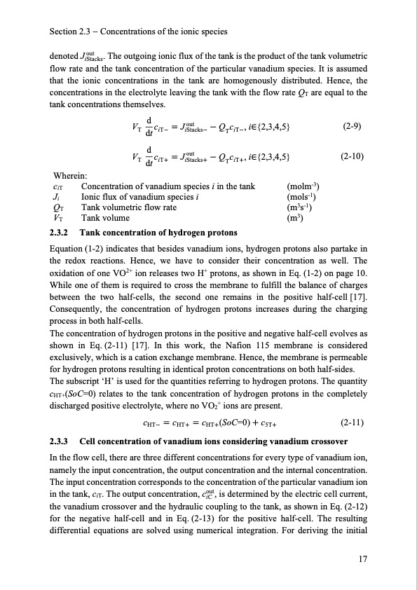
Section 2.3 Concentrations of the ionic species denoted J out . The outgoing ionic flux of the tank is the product of the tank volumetric iStacks flow rate and the tank concentration of the particular vanadium species. It is assumed that the ionic concentrations in the tank are homogenously distributed. Hence, the concentrations in the electrolyte leaving the tank with the flow rate QT are equal to the tank concentrations themselves. Wherein: ciT Ji QT VT 2.3.2 Concentration of vanadium species i in the tank Ionic flux of vanadium species i Tank volumetric flow rate Tank volume Tank concentration of hydrogen protons (molm-3) (mols-1) (m3s-1) (m3) .V dc Jout T dt iT iStacks .V dc Jout T dt iT iStacks Q c ,i∈{2,3,4,5} T iT Q c ,i∈{2,3,4,5} T iT (2-9) (2-10) Equation (1-2) indicates that besides vanadium ions, hydrogen protons also partake in the redox reactions. Hence, we have to consider their concentration as well. The oxidation of one VO2+ ion releases two H+ protons, as shown in Eq. (1-2) on page 10. While one of them is required to cross the membrane to fulfill the balance of charges between the two half-cells, the second one remains in the positive half-cell [17]. Consequently, the concentration of hydrogen protons increases during the charging process in both half-cells. The concentration of hydrogen protons in the positive and negative half-cell evolves as shown in Eq. (2-11) [17]. In this work, the Nafion 115 membrane is considered exclusively, which is a cation exchange membrane. Hence, the membrane is permeable for hydrogen protons resulting in identical proton concentrations on both half-sides. The subscript ‘H’ is used for the quantities referring to hydrogen protons. The quantity cHT+(SoC=0) relates to the tank concentration of hydrogen protons in the completely discharged positive electrolyte, where no VO2+ ions are present. cHT cHT cHT(SoC=0) c5T (2-11) 2.3.3 Cell concentration of vanadium ions considering vanadium crossover In the flow cell, there are three different concentrations for every type of vanadium ion, namely the input concentration, the output concentration and the internal concentration. The input concentration corresponds to the concentration of the particular vanadium ion in the tank, ciT. The output concentration, cout, is determined by the electric cell current, iC the vanadium crossover and the hydraulic coupling to the tank, as shown in Eq. (2-12) for the negative half-cell and in Eq. (2-13) for the positive half-cell. The resulting differential equations are solved using numerical integration. For deriving the initial 17PDF Image | Model-based Design Vanadium Redox Flow Batteries

PDF Search Title:
Model-based Design Vanadium Redox Flow BatteriesOriginal File Name Searched:
10-5445IR1000070670.pdfDIY PDF Search: Google It | Yahoo | Bing
Salgenx Redox Flow Battery Technology: Salt water flow battery technology with low cost and great energy density that can be used for power storage and thermal storage. Let us de-risk your production using our license. Our aqueous flow battery is less cost than Tesla Megapack and available faster. Redox flow battery. No membrane needed like with Vanadium, or Bromine. Salgenx flow battery
| CONTACT TEL: 608-238-6001 Email: greg@salgenx.com | RSS | AMP |