PDF Publication Title:
Text from PDF Page: 076
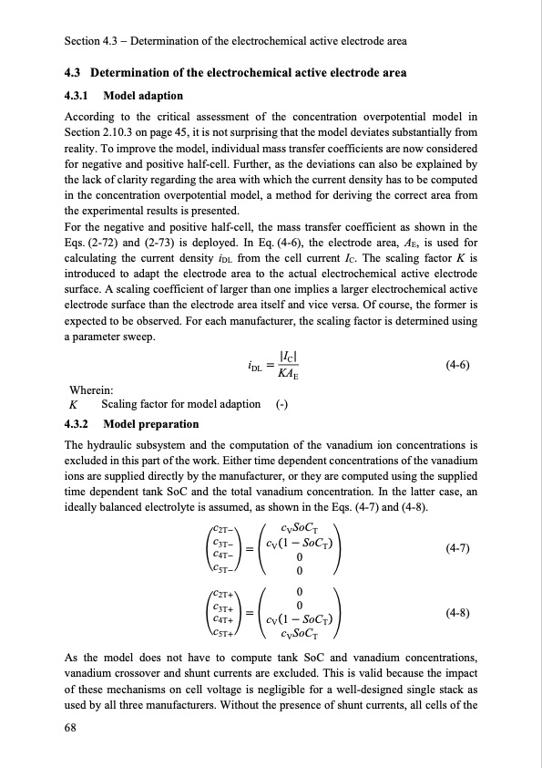
Section 4.3 Determination of the electrochemical active electrode area 4.3 Determination of the electrochemical active electrode area 4.3.1 Model adaption According to the critical assessment of the concentration overpotential model in Section 2.10.3 on page 45, it is not surprising that the model deviates substantially from reality. To improve the model, individual mass transfer coefficients are now considered for negative and positive half-cell. Further, as the deviations can also be explained by the lack of clarity regarding the area with which the current density has to be computed in the concentration overpotential model, a method for deriving the correct area from the experimental results is presented. For the negative and positive half-cell, the mass transfer coefficient as shown in the Eqs. (2-72) and (2-73) is deployed. In Eq. (4-6), the electrode area, AE, is used for calculating the current density iDL from the cell current IC. The scaling factor K is introduced to adapt the electrode area to the actual electrochemical active electrode surface. A scaling coefficient of larger than one implies a larger electrochemical active electrode surface than the electrode area itself and vice versa. Of course, the former is expected to be observed. For each manufacturer, the scaling factor is determined using a parameter sweep. iDL |IC| KAE Wherein: K Scaling factor for model adaption (-) 4.3.2 Model preparation (4-6) The hydraulic subsystem and the computation of the vanadium ion concentrations is excluded in this part of the work. Either time dependent concentrations of the vanadium ions are supplied directly by the manufacturer, or they are computed using the supplied time dependent tank SoC and the total vanadium concentration. In the latter case, an ideally balanced electrolyte is assumed, as shown in the Eqs. (4-7) and (4-8). (4-7) (4-8) As the model does not have to compute tank SoC and vanadium concentrations, vanadium crossover and shunt currents are excluded. This is valid because the impact of these mechanisms on cell voltage is negligible for a well-designed single stack as used by all three manufacturers. Without the presence of shunt currents, all cells of the 68 c2T cV SoCT c3T cV1 SoCT c4T 0 c5T 0 c2T 0 c3T 0 c4T cV1 SoCT c5T cV SoCTPDF Image | Model-based Design Vanadium Redox Flow Batteries

PDF Search Title:
Model-based Design Vanadium Redox Flow BatteriesOriginal File Name Searched:
10-5445IR1000070670.pdfDIY PDF Search: Google It | Yahoo | Bing
Salgenx Redox Flow Battery Technology: Salt water flow battery technology with low cost and great energy density that can be used for power storage and thermal storage. Let us de-risk your production using our license. Our aqueous flow battery is less cost than Tesla Megapack and available faster. Redox flow battery. No membrane needed like with Vanadium, or Bromine. Salgenx flow battery
| CONTACT TEL: 608-238-6001 Email: greg@salgenx.com | RSS | AMP |