PDF Publication Title:
Text from PDF Page: 109
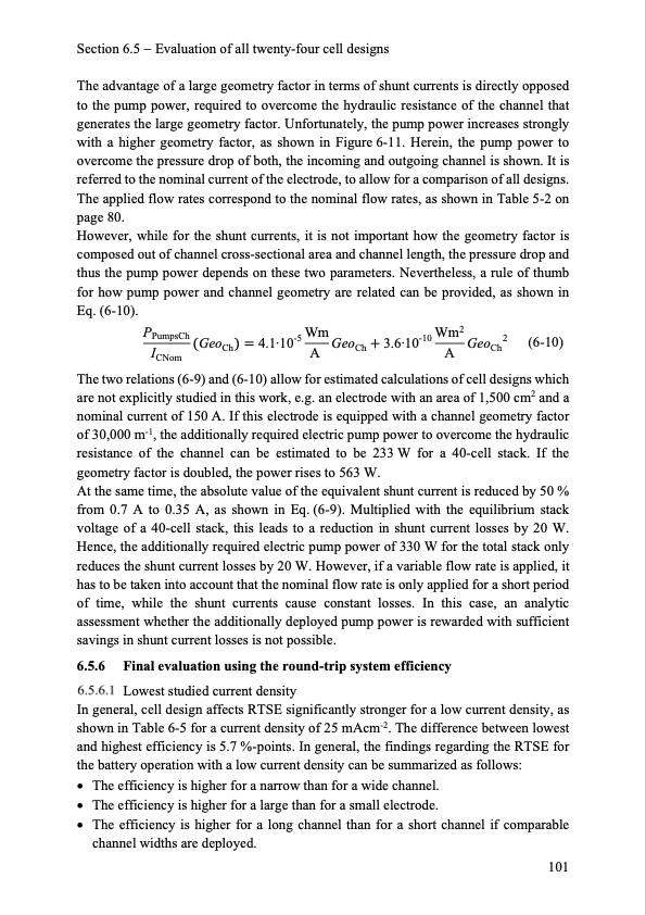
Section 6.5 Evaluation of all twenty-four cell designs The advantage of a large geometry factor in terms of shunt currents is directly opposed to the pump power, required to overcome the hydraulic resistance of the channel that generates the large geometry factor. Unfortunately, the pump power increases strongly with a higher geometry factor, as shown in Figure 6-11. Herein, the pump power to overcome the pressure drop of both, the incoming and outgoing channel is shown. It is referred to the nominal current of the electrode, to allow for a comparison of all designs. The applied flow rates correspond to the nominal flow rates, as shown in Table 5-2 on page 80. However, while for the shunt currents, it is not important how the geometry factor is composed out of channel cross-sectional area and channel length, the pressure drop and thus the pump power depends on these two parameters. Nevertheless, a rule of thumb for how pump power and channel geometry are related can be provided, as shown in Eq. (6-10). PPumpsCh -5 Wm -10 Wm2 2 I GeoCh 4.1·10 A GeoCh 3.6·10 A GeoCh CNom (6-10) The two relations (6-9) and (6-10) allow for estimated calculations of cell designs which are not explicitly studied in this work, e.g. an electrode with an area of 1,500 cm2 and a nominal current of 150 A. If this electrode is equipped with a channel geometry factor of 30,000 m-1, the additionally required electric pump power to overcome the hydraulic resistance of the channel can be estimated to be 233 W for a 40-cell stack. If the geometry factor is doubled, the power rises to 563 W. At the same time, the absolute value of the equivalent shunt current is reduced by 50 % from 0.7 A to 0.35 A, as shown in Eq. (6-9). Multiplied with the equilibrium stack voltage of a 40-cell stack, this leads to a reduction in shunt current losses by 20 W. Hence, the additionally required electric pump power of 330 W for the total stack only reduces the shunt current losses by 20 W. However, if a variable flow rate is applied, it has to be taken into account that the nominal flow rate is only applied for a short period of time, while the shunt currents cause constant losses. In this case, an analytic assessment whether the additionally deployed pump power is rewarded with sufficient savings in shunt current losses is not possible. 6.5.6 Final evaluation using the round-trip system efficiency Lowest studied current density In general, cell design affects RTSE significantly stronger for a low current density, as shown in Table 6-5 for a current density of 25 mAcm-2. The difference between lowest and highest efficiency is 5.7 %-points. In general, the findings regarding the RTSE for the battery operation with a low current density can be summarized as follows: Theefficiencyishigherforanarrowthanforawidechannel. Theefficiencyishigherforalargethanforasmallelectrode. The efficiency is higher for a long channel than for a short channel if comparable channel widths are deployed. 101PDF Image | Model-based Design Vanadium Redox Flow Batteries

PDF Search Title:
Model-based Design Vanadium Redox Flow BatteriesOriginal File Name Searched:
10-5445IR1000070670.pdfDIY PDF Search: Google It | Yahoo | Bing
Salgenx Redox Flow Battery Technology: Salt water flow battery technology with low cost and great energy density that can be used for power storage and thermal storage. Let us de-risk your production using our license. Our aqueous flow battery is less cost than Tesla Megapack and available faster. Redox flow battery. No membrane needed like with Vanadium, or Bromine. Salgenx flow battery
| CONTACT TEL: 608-238-6001 Email: greg@salgenx.com | RSS | AMP |