PDF Publication Title:
Text from PDF Page: 126
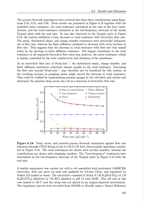
The porous electrode impedances were resolved into their three contributions using Equa- tions 3.54, 3.55, and 3.56. These results are presented in Figure 6.18 together with the modelled series resistance, the total resistance calculated as the sum of the four contri- butions, and the total resistance estimated as the low-frequency intercept of the model Nyquist plots with the real axis. As was also observed on the Nyquist plots in Figure 6.16, the system exhibited a clear decrease in total resistance with electrolyte flow rate. The series, distributed ohmic, and charge transfer resistances were practically independ- ent of flow rate, whereas the finite diffusion continued to decrease with every increase in flow rate. This suggests that the decrease in total resistance with flow rate was caused solely by the decrease in finite diffusion resistance. The largest contributor to the total resistance at all employed electrolyte flow rates was, however, the series resistance, which is mainly controlled by the ionic conductivity and thickness of the membrane. At an electrolyte flow rate of 50mLmin−1, the distributed ohmic, charge transfer, and finite diffusion resistances contribute almost equally to the total resistance. Increasing the flow rate beyond 50mLmin−1 may therefore not be beneficial for this system, as the resulting increase in pumping losses might exceed the decrease in total resistance. This could be verified by implementing pressure gauges at the cell inlets and outlets and determine the pressure drop across the cell as a function of electrolyte flow rate. Figure 6.18: Total, series, and resolved porous electrode resistances against flow rate obtained through CNLS fitting of the 0.1 M/0.1 M ferri-/ferrocyanide impedance presen- ted in Figure 6.16. The total resistances are shown with circular markers, whereas the contributions are shown with triangular markers. The "Low-frequency" resistances were determined as the low-frequency intercept of the Nyquist plots in Figure 6.16 with the real axis. A similar experiment was carried out with a cell assembled with pretreated 1186HCBA electrodes, with one piece on each side gasketed by 0.8mm Viton, and separated by Nafion 212 soaked in water. The electrolyte consisted of 50 mL 0.1 M K3[Fe(CN)6]+0.1 M K4[Fe(CN)6] dissolved in 1M KCl adjusted to pH 12 with KOH. The cell was in this case heated to 30 ◦C and the setup was not placed in an oxygen-deprived environment. The impedance spectra were recorded from 316 kHz to 30 mHz using a Gamry Reference 6.2. Results and Discussion 105PDF Image | Organic Redox Flow Batteries 2023
PDF Search Title:
Organic Redox Flow Batteries 2023Original File Name Searched:
PhD_thesis_final_dorhoff_4_.pdfDIY PDF Search: Google It | Yahoo | Bing
Salgenx Redox Flow Battery Technology: Salt water flow battery technology with low cost and great energy density that can be used for power storage and thermal storage. Let us de-risk your production using our license. Our aqueous flow battery is less cost than Tesla Megapack and available faster. Redox flow battery. No membrane needed like with Vanadium, or Bromine. Salgenx flow battery
| CONTACT TEL: 608-238-6001 Email: greg@salgenx.com | RSS | AMP |