PDF Publication Title:
Text from PDF Page: 133
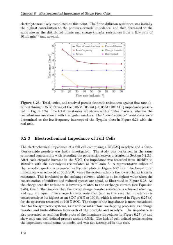
Chapter 6. Electrochemical Impedance of Single Flow Cells electrolyte was likely completed at this point. The finite diffusion resistance was initially the highest contribution to the porous electrode impedance, and then decreased to the same size as the distributed ohmic and charge transfer resistances from a flow rate of 30mLmin−1 andupward. Figure 6.26: Total, series, and resolved porous electrode resistances against flow rate ob- tained through CNLS fitting of the 0.05 M DBEAQ+0.05 M DBEAHQ impedance presen- ted in Figure 6.24. The total resistances are shown with circular markers, whereas the contributions are shown with triangular markers. The "Low-frequency" resistances were determined as the low-frequency intercept of the Nyquist plots in Figure 6.24 with the real axis. 6.2.3 Electrochemical Impedance of Full Cells The electrochemical impedance of a full cell comprising a DBEAQ negolyte and a ferro- /ferricyanide posolyte was lastly investigated. The study was performed in the same setup and concurrently with recording the polarisation curves presented in Section 5.2.2.3. After each stepwise increase in the SOC, the impedance was recorded from 100kHz to 100 mHz with the electrolytes recirculated at 50 mL min−1. A representative subset of the recorded spectra is presented as Nyquist plots in Figure 6.27 (a). The lowest total impedance was achieved at 50 % SOC where the system exhibits the lowest charge transfer resistance. This is related to the exchange current, which is at its highest value when the concentration of oxidised and reduced species are equal, as illustrated in Figure 6.28. As the charge transfer resistance is inversely related to the exchange current (see Equation 3.46), this further implies that the lowest charge transfer resistance is achieved when cOx and cRed are equal. The charge transfer resistance (and in this case the impedance) is consequently at its highest at an SOC of 0 % or 100 %, which is observed in Figure 6.27 (a) for the spectrum recorded at 100 % SOC. The shape of the impedance is more convoluted than for the symmetric systems, as it now consists of four overlapping processes, i.e. charge transfer and finite diffusion from each of the posolyte and negolyte. The impedance is also presented as semi-log Bode plots of the imaginary impedance in Figure 6.27 (b) and show only one well-defined process around 0.5 Hz. The lack of well-defined peaks renders the impedance troublesome to model and was not attempted in this case. 112PDF Image | Organic Redox Flow Batteries 2023
PDF Search Title:
Organic Redox Flow Batteries 2023Original File Name Searched:
PhD_thesis_final_dorhoff_4_.pdfDIY PDF Search: Google It | Yahoo | Bing
Salgenx Redox Flow Battery Technology: Salt water flow battery technology with low cost and great energy density that can be used for power storage and thermal storage. Let us de-risk your production using our license. Our aqueous flow battery is less cost than Tesla Megapack and available faster. Redox flow battery. No membrane needed like with Vanadium, or Bromine. Salgenx flow battery
| CONTACT TEL: 608-238-6001 Email: greg@salgenx.com | RSS | AMP |