PDF Publication Title:
Text from PDF Page: 017
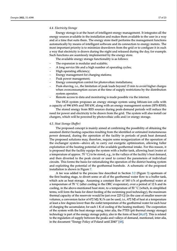
Energies 2022, 15, 6398 17 of 23 4.4. Electricity Storage Energy storage is at the heart of intelligent energy management. It integrates all the energy sources available in the installation and makes them available to the user in a way and at a time that suits them. The energy store itself performs the management functions automatically by means of intelligent software and its connection to energy meters. The most important priority is to minimize drawdown from the grid or to configure it in such a way that electricity is drawn during the night and released during the day, for example. Such functions are seamlessly implemented by the energy store. The available energy storage functionality is as follows: - The expansion is modular and scalable; - A long service life and a high number of operating cycles; - High operating efficiency; - Energy management for charging stations; - Peak power management; - Energy consumption control for photovoltaic installations; - Peak-shaving, i.e., the limitation of peak loads beyond 15 min to avoid higher charges when overconsumption occurs at the time of supply restrictions by the distribution system operator; - Remote access to data and monitoring is made possible via the internet. The HGS system proposes an energy storage system using lithium-ion cells with a capacity of 996 kWh and 500 kW, along with an energy management system (SPS-R500). The stored energy from RES sources during peak-demand periods will reduce the need for power and electricity to be drawn from the grid. The system will also install car chargers, which will be powered by photovoltaic cells and/or energy storage. 4.5. Heat Storage (Buffer) The proposed concept is mainly aimed at confirming the possibility of obtaining the assumed district heating capacities resulting from the identified or estimated instantaneous power demand, during the operation of the facility in periods of peak heat demand. The proposed solutions may, therefore, require some reorganization of the operation of the exchanger system—above all, to carry out exergetic optimization, allowing fuller exploitation of the heating potential of the available geothermal intake. For this reason, it is proposed that the facility equips the system with a buffer tank, allowing heat (water at a temperature of approx. 70 ◦C) to be stored, e.g., in the valleys of the facility’s heat demand, and then diverted to the peak circuit or used to correct the parameters of individual circuits. This forms the basis for rationalizing the operation of the district heating system and exploiting the potential of the geothermal borehole. A schematic of the proposed installation is shown in Figure 7. A tee was added to the process line described in Section 3.2 (Figure 5) upstream of the first heating stage, to divert some or all of the geothermal water flow to a buffer tank, which acts as heat storage. Assuming a constant flow of 160 t/h of geothermal water at a temperature of 78 ◦C (after cooling in the ORC evaporator), over a period of 12 h and its cooling, in the above-mentioned heat store, to a temperature of 50 ◦C (which, in simplified terms, will form the basis for direct feeding of the swimming pool technology), the maximum thermal capacity of the reservoir would be just over 225 GJ (in the case of smaller reservoir volumes, a conversion factor of 672 MJ/K/h can be used, i.e., 672 MJ of heat at a temperature at least a few degrees lower than the outlet temperature of the geothermal water for each hour of charging the accumulator, for each 1 K of cooling of the heating medium). The cooperation of the system with the heat storage using, inter alia, the PTES (pit thermal energy storage) technology is part of the energy storage policy, also in the form of heat [46,47]. This is related to the regulation of supply between the peaks and valleys of demand, mentioned, inter alia, in the document “Energy Policy of Poland until 2040” [48].PDF Image | Combined Renewable Energy Resources System Geothermal
PDF Search Title:
Combined Renewable Energy Resources System GeothermalOriginal File Name Searched:
energies-15-06398.pdfDIY PDF Search: Google It | Yahoo | Bing
Turbine and System Plans CAD CAM: Special for this month, any plans are $10,000 for complete Cad/Cam blueprints. License is for one build. Try before you buy a production license. More Info
Waste Heat Power Technology: Organic Rankine Cycle uses waste heat to make electricity, shaft horsepower and cooling. More Info
All Turbine and System Products: Infinity Turbine ORD systems, turbine generator sets, build plans and more to use your waste heat from 30C to 100C. More Info
CO2 Phase Change Demonstrator: CO2 goes supercritical at 30 C. This is a experimental platform which you can use to demonstrate phase change with low heat. Includes integration area for small CO2 turbine, static generator, and more. This can also be used for a GTL Gas to Liquids experimental platform. More Info
Introducing the Infinity Turbine Products Infinity Turbine develops and builds systems for making power from waste heat. It also is working on innovative strategies for storing, making, and deploying energy. More Info
Need Strategy? Use our Consulting and analyst services Infinity Turbine LLC is pleased to announce its consulting and analyst services. We have worked in the renewable energy industry as a researcher, developing sales and markets, along with may inventions and innovations. More Info
Made in USA with Global Energy Millennial Web Engine These pages were made with the Global Energy Web PDF Engine using Filemaker (Claris) software.
Sand Battery Sand and Paraffin for TES Thermo Energy Storage More Info
| CONTACT TEL: 608-238-6001 Email: greg@infinityturbine.com | RSS | AMP |