PDF Publication Title:
Text from PDF Page: 005
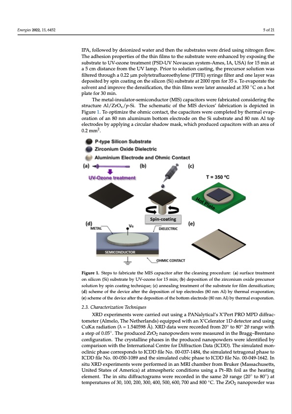
Energies 2022, 15, 6452 stirring for a minimum of 1 h. The molar proportion between urea and the zirconium oxide precursor was 5:3 to ensure the redox stoichiometry of the reaction. The powder was produced considering 10 mL of the combustion solution with the same concentration and transferred to an alumina ceramic crucible for further annealing in an air furnace at 350°Cfor1h. 5of21 As for the thin films, and prior to the ZrOx deposition, a 2.5 × 2.5 cm p-type single crystal 100-oriented silicon substrate (resistivity ≅ 1–2 Ω·cm) was cleaned with acetone for 10 min in an ultrasonic cleaning bath at 60 °C. This cleaning process was repeated with IPA, followed by deionized water and then the substrates were dried using nitrogen flow. IPA, followed by deionized water and then the substrates were dried using nitrogen flow. The adhesion properties of the thin films to the substrate were enhanced by exposing the The adhesion properties of the thin films to the substrate were enhanced by exposing the substrate to UV-ozone treatment (PSD-UV Novascan system-Ames, IA, USA) for 15 min at substrate to UV-ozone treatment (PSD-UV Novascan system-Ames, IA, USA) for 15 min a 5 cm distance from the UV lamp. Prior to solution casting, the precursor solution was at a 5 cm distance from the UV lamp. Prior to solution casting, the precursor solution was filtered through a 0.22 μm polytetrafluoroethylene (PTFE) syringe filter and one layer was filtered through a 0.22 μm polytetrafluoroethylene (PTFE) syringe filter and one layer was deposited by spin coating on the silicon (Si) substrate at 2000 rpm for 35 s. To evaporate the deposited by spin coating on the silicon (Si) substrate at 2000 rpm for 35 s. To evaporate solvent and improve the densification, the thin films were later annealed at 350 ◦C on a hot the solvent and improve the densification, the thin films were later annealed at 350 °C on plate for 30 min. a hot plate for 30 min. The metal-insulator-semiconductor (MIS) capacitors were fabricated considering the The metal-insulator-semiconductor (MIS) capacitors were fabricated considering the structure Al/ZrOx/p-Si. The schematic of the MIS devices’ fabrication is depicted in structure Al/ZrOx/p-Si. The schematic of the MIS devices’ fabrication is depicted in Figure Figure 1. To optimize the ohmic contact, the capacitors were completed by thermal evap- 1. To optimize the ohmic contact, the capacitors were completed by thermal evaporation oration of an 80 nm aluminum bottom electrode on the Si substrate and 80 nm Al top of an 80 nm aluminum bottom electrode on the Si substrate and 80 nm Al top electrodes electrodes by applying a circular shadow mask, which produced capacitors with an area of by applying2 a circular shadow mask, which produced capacitors with an area of 0.2 mm2. 0.2 mm . FiguFreig1u.rSete1p.sStoepfasbtroicfatbertihcaetMetIhSecaMpIaScictaopracfitteorrthaeftecrletahneincgleparnoincegdpuroec:e(ad)usruer:f(aac)esturerafatmceetnrteaotnment silicon (Si) substrate by UV-ozone for 15 min; (b) deposition of the zirconium oxide precursor on silicon (Si) substrate by UV-ozone for 15 min; (b) deposition of the zirconium oxide precursor solution by spin coating technique; (c) annealing treatment of the substrate for film densification; solution by spin coating technique; (c) annealing treatment of the substrate for film densification; (d) scheme of the device after the deposition of top electrodes (80 nm Al) by thermal evaporation; (d) scheme of the device after the deposition of top electrodes (80 nm Al) by thermal evaporation; (e) scheme of the device after the deposition of the bottom electrode (80 nm Al) by thermal (e) scheme of the device after the deposition of the bottom electrode (80 nm Al) by thermal evaporation. evaporation. 2.3. Characterization Techniques diffrCacutKomαeratedria(Atiolmne(lλo=, T1h.5e4N05e9th8eÅrl)a.nXdRsD) edqautiappweedrewrietchoardneXd’Cfreolmera2t0ort1oD80det2eθctroarnagnedwith a step of 0.05◦. The produced ZrO2 nanopowders were measured in the Bragg–Brentano configuration. The crystalline phases in the produced nanopowders were identified by comparison with the International Centre for Diffraction Data (ICDD). The simulated mon- oclinic phase corresponds to ICDD file No. 00-037-1484, the simulated tetragonal phase to ICDD file No. 00-050-1089 and the simulated cubic phase to ICDD file No. 00-049-1642. In situ XRD experiments were performed in an MRI chamber from Bruker (Massachusetts, United States of America) at atmospheric conditions using a Pt–Rh foil as the heating element. The in situ diffractograms were recorded in the same 2θ range (20◦ to 80◦) at temperatures of 30, 100, 200, 300, 400, 500, 600, 700 and 800 ◦C. The ZrO2 nanopowder was 2.3. Characterization Techniques XRD experiments were carried out using a PANalytical’s X’Pert PRO MPD diffrac- toXmRDeterex(Apelmrimeleon,tTshewNereethecralrarniedds)oequutipupsiendgwaithPaAnNXa’lCyetilcearal’tsorX1’DPedrtetePcRtoOraMndPDusing ◦◦PDF Image | Comparison between Solution-Based Synthesis Methods of ZrO2
PDF Search Title:
Comparison between Solution-Based Synthesis Methods of ZrO2Original File Name Searched:
energies-15-06452.pdfDIY PDF Search: Google It | Yahoo | Bing
Turbine and System Plans CAD CAM: Special for this month, any plans are $10,000 for complete Cad/Cam blueprints. License is for one build. Try before you buy a production license. More Info
Waste Heat Power Technology: Organic Rankine Cycle uses waste heat to make electricity, shaft horsepower and cooling. More Info
All Turbine and System Products: Infinity Turbine ORD systems, turbine generator sets, build plans and more to use your waste heat from 30C to 100C. More Info
CO2 Phase Change Demonstrator: CO2 goes supercritical at 30 C. This is a experimental platform which you can use to demonstrate phase change with low heat. Includes integration area for small CO2 turbine, static generator, and more. This can also be used for a GTL Gas to Liquids experimental platform. More Info
Introducing the Infinity Turbine Products Infinity Turbine develops and builds systems for making power from waste heat. It also is working on innovative strategies for storing, making, and deploying energy. More Info
Need Strategy? Use our Consulting and analyst services Infinity Turbine LLC is pleased to announce its consulting and analyst services. We have worked in the renewable energy industry as a researcher, developing sales and markets, along with may inventions and innovations. More Info
Made in USA with Global Energy Millennial Web Engine These pages were made with the Global Energy Web PDF Engine using Filemaker (Claris) software.
Sand Battery Sand and Paraffin for TES Thermo Energy Storage More Info
| CONTACT TEL: 608-238-6001 Email: greg@infinityturbine.com | RSS | AMP |