PDF Publication Title:
Text from PDF Page: 003
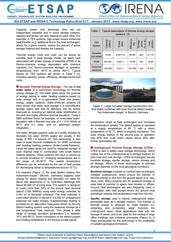
ENERGY TECHNOLOGY SYSTEM ANALYSIS PROGRAMME IEA-ETSAP and IRENA © Technology-Policy Brief E17 – January 2013 - www.etsap.org, www.irena.org Capacity, power and discharge time are not independent variables and in some storage systems, capacity and power can also depend on each other. For example, in TES systems, high power means enhanced heat transfer (e.g. additional fins in the heat exchanger), which, for a given volume, reduce the amount of active storage material and thereby the capacity. Thermal energy (heat and cold) can be stored as sensible heat in heat storage media, as latent heat associated with phase change of materials (PCM) or as thermo-chemical energy associated with chemical reactions (i.e. thermo-chemical storage) at operation temperatures from -40°C to above 400°C. Typical figures for TES systems are shown in Table 1 [1], including capacity, power, efficiency, storage period and costs. Sensible Thermal Energy Storage - The use of hot water tanks is a well-known technology for thermal energy storage [2]. Hot water tanks serve the purpose of energy saving in water heating systems based on solar energy and in co-generation (heat and power) energy supply systems. State-of-the-art projects [3] have shown that water tank storage is a cost-effective storage option and that its efficiency can be further improved by ensuring an optimal water stratification in the tank and highly effective thermal insulation. Today’s R&D activities focus, for example, on evacuated super- insulation with a thermal loss rate of λ = 0.01 W/mK at 90°C and 0,1 mbar, and on optimised system integration. Hot water storage systems used as a buffer storage for domestic hot water (DHW) supply are usually in the range of 500 l to several m3. This technology is also used in solar thermal installations for DHW combined with building heating systems (Solar-Combi-Systems). Large hot water tanks are used for seasonal storage of solar thermal heat in combination with small district heating systems. These systems can have a volume up to several thousand m3. Charging temperatures are in the range of 80-90°C. The usable temperature difference can be enhanced by the use of heat pumps for discharging (down to temperatures around 10 °C). For example (Figure 1), the solar district heating “Am Ackermann-bogen” (Munich, Germany) supplies solar energy for space heating and domestic hot water for about 320 apartments in 12 multi-story dwellings with about 30,400 m2 of living area. The system is designed to cover more than 50% of the annual heat demand (about 2,000 MWh/a) using solar energy collected by 2,761 m2 of flat-plate collectors. The heat collected is used either directly or stored in a 6,000 m3 underground seasonal hot water storage. Supplementary heating is provided by an absorption heat pump driven by the city district heating system using the seasonal storage as a low temperature heat reservoir. This allows a wide range of storage operation temperature (i.e. between 10°C and 90°C). Direct connection of the district system and heating installations in the houses avoids typical Table 1 Typical parameters of thermal energy storage systems [1] TES System Sensible (hot water) 10-50 0.001-10 50-90 d/m 0.1-10 PCM 50-150 0.001-1 75-90 h/m 10-50 Chemical reactions 120-250 0.01-1 75-100 h/d 8-100 3 Giorgio.Simbolotti@enea.it, Giancarlo Tosato (gct@etsap.org) and Dolf Gielen (dgielen@irena.org), Project Co-ordinators Figure 1 final state) combined with solar thermal district heating Large hot-water storage (construction and “Am Ackermann-bogen” in Munich, Germany temperature drops at heat exchangers and increases the temperature spread. The district system is operated at a supply temperature of 60 °C with a return temperature of 30 °C, which is properly monitored. The solar energy fraction in the second year of operation was 45% and could reach values above 50% after further optimisation [4]. Underground Thermal Energy Storage (UTES) - UTES is also a widely used storage technology, which makes use of the underground as a storage medium for both heat and cold storage. UTES technologies include borehole storage, aquifer storage, cavern storage and pit storage. Which of these technologies is selected strongly depends on the local geological conditions. Borehole storage is based on vertical heat exchangers installed underground, which ensure the transfer of thermal energy to and from the ground layers (e.g. clay, sand, rock). Many projects aim for seasonal storage of solar heat in summer to space heat houses or offices. Ground heat exchangers are also frequently used in combination with heat pumps where the ground heat exchanger extracts low-temperature heat from the soil. Aquifer storage uses a natural underground water- permeable layer as a storage medium. The transfer of thermal energy is achieved by mass transfer (i.e. extracting and re-injecting water from/into the underground layer). Most applications deal with the storage of winter cold to be used for the cooling of large office buildings and industrial processes (Figure 2). A major prerequisite for this technology is the availability of suitable geological formations. Please send comments to Andreas Hauer (hauer@muc.zae-bayern.de), Author, and to Capacity (kWh/t) Power MW) Efficiency (%) Storage period (h, d, m) Cost (€/kWh)PDF Image | ENERGY TECHNOLOGY SYSTEM ANALYSIS
PDF Search Title:
ENERGY TECHNOLOGY SYSTEM ANALYSISOriginal File Name Searched:
E17IR-ThEnergy Stor_AH_Jan2013_final_GSOK.pdfDIY PDF Search: Google It | Yahoo | Bing
Turbine and System Plans CAD CAM: Special for this month, any plans are $10,000 for complete Cad/Cam blueprints. License is for one build. Try before you buy a production license. More Info
Waste Heat Power Technology: Organic Rankine Cycle uses waste heat to make electricity, shaft horsepower and cooling. More Info
All Turbine and System Products: Infinity Turbine ORD systems, turbine generator sets, build plans and more to use your waste heat from 30C to 100C. More Info
CO2 Phase Change Demonstrator: CO2 goes supercritical at 30 C. This is a experimental platform which you can use to demonstrate phase change with low heat. Includes integration area for small CO2 turbine, static generator, and more. This can also be used for a GTL Gas to Liquids experimental platform. More Info
Introducing the Infinity Turbine Products Infinity Turbine develops and builds systems for making power from waste heat. It also is working on innovative strategies for storing, making, and deploying energy. More Info
Need Strategy? Use our Consulting and analyst services Infinity Turbine LLC is pleased to announce its consulting and analyst services. We have worked in the renewable energy industry as a researcher, developing sales and markets, along with may inventions and innovations. More Info
Made in USA with Global Energy Millennial Web Engine These pages were made with the Global Energy Web PDF Engine using Filemaker (Claris) software.
Sand Battery Sand and Paraffin for TES Thermo Energy Storage More Info
| CONTACT TEL: 608-238-6001 Email: greg@infinityturbine.com | RSS | AMP |