PDF Publication Title:
Text from PDF Page: 006
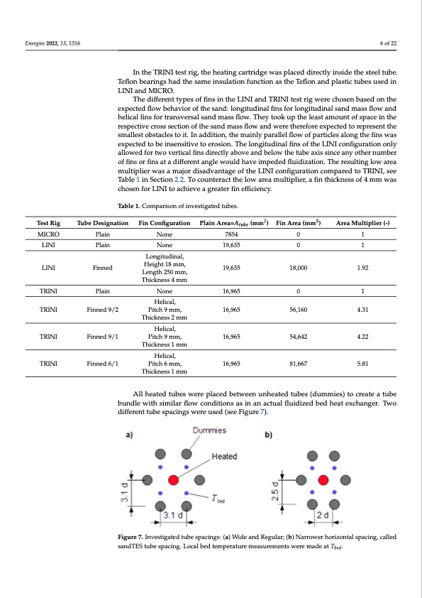
Energies 2022, 15, x FOR PEER REVIEW 6 of 22 Energies 2022, 15, 1316 6 of 22 Test Rig Table 1. Comparison of investigated tubes. Table 1. Comparison of investigated tubes. Tube Designation Fin Configuration Plain Area = 𝑨 (mm2) Fin Area (mm2) Area Multiplier (-) Test Rig Tube Designation Fin Configuration 𝒕𝒖𝒃𝒆 2 Plain Area=Atube (mm ) 2 Fin Area (mm ) Area Multiplier (-) MICRO Plain None 7854 0 0 18,000 18,000 1 In the TRINI test rig, the heating cartridge was placed directly inside the steel tube. In the TRINI test rig, the heating cartridge was placed directly inside the steel tube. Teflon bearings had the same insulation function as the Teflon and plastic tubes used in Teflon bearings had the same insulation function as the Teflon and plastic tubes used in LINI and MICRO. LINI and MICRO. The different types of fins in the LINI and TRINI test rig were chosen based on the The different types of fins in the LINI and TRINI test rig were chosen based on the expected flow behavior of the sand: longitudinal fins for longitudinal sand mass flow and expected flow behavior of the sand: longitudinal fins for longitudinal sand mass flow and helical fins for transversal sand mass flow. They took up the least amount of space in the helical fins for transversal sand mass flow. They took up the least amount of space in the respective cross section of the sand mass flow and were therefore expected to represent respective cross section of the sand mass flow and were therefore expected to represent the the smallest obstacles to it. In addition, the mainly parallel flow of particles along the fins smallest obstacles to it. In addition, the mainly parallel flow of particles along the fins was was expected to be insensitive to erosion. The longitudinal fins of the LINI configuration expected to be insensitive to erosion. The longitudinal fins of the LINI configuration only only allowed for two vertical fins directly above and below the tube axis since any other allowed for two vertical fins directly above and below the tube axis since any other number number of fins or fins at a different angle would have impeded fluidization. The resulting of fins or fins at a different angle would have impeded fluidization. The resulting low area low area multiplier was a major disadvantage of the LINI configuration compared to multiplier was a major disadvantage of the LINI configuration compared to TRINI, see TRINI, see Table 1 in Section 2.2. To counteract the low area multiplier, a fin thickness of Table 1 in Section 2.2. To counteract the low area multiplier, a fin thickness of 4 mm was 4 mm was chosen for LINI to achieve a greater fin efficiency. chosen for LINI to achieve a greater fin efficiency. MICRO Plain None 7854 0 0 1 LINI Plain None 19,635 1 LINI LINI LINI Plain Finned Finned None 19,635 19,635 19,635 1 1.92 1.92 TRINI Plain None 16,965 0 56,160 1 TRINI Finned 9/2 Helical, TRINI Finned 9/2 Pitch 9 mm, 16,965 4.31 Helical, TTRRININII FinFninended9/91/1 PiPtcihtch99mmm,, 1166,9,69565 16,965 545,64,2642 44.2.22 81,667 5.81 Longitudinal, Longitudinal, Height 18 mm, Height 18 mm, Length 250 mm, Length 250 mm, Thickness 4 mm Thickness 4 mm TRINI Plain None 16,965 0 56,160 1 Helical, Pitch 9 mm, 16,965 4.31 Thickness 2 mm Thickness 2 mm Helical, Thickness 1 mm Thickness 1 mm HHeleicliacla,l, TRINI Finned 6/1 Pitch 6 mm, TRINI Finned 6/1 Pitch 6 mm, 16,965 All heated tubes were placed between unheated tubes (dummies) to create a tube Thickness 1 mm 81,667 5.81 Thickness 1 mm All heated tubes were placed between unheated tubes (dummies) to create a tube bundle with similar flow conditions as in an actual fluidized bed heat exchanger. Two bundle with similar flow conditions as in an actual fluidized bed heat exchanger. Two diifferentt ttube spaciingss werreeusseed((sseeeFiigurree77)). . Figure 7. Investigated tube spacings: (a) Wide and Regular; (b) Narrower horizontal spacing, called Figure 7. Investigated tube spacings: (a) Wide and Regular; (b) Narrower horizontal spacing, called sandTES tube spacing. Local bed temperature measurements were made at 𝑇. sandTES tube spacing. Local bed temperature measurements were made at Tbed.PDF Image | Heat Transfer between Finned Tubes
PDF Search Title:
Heat Transfer between Finned TubesOriginal File Name Searched:
energies-15-01316.pdfDIY PDF Search: Google It | Yahoo | Bing
Turbine and System Plans CAD CAM: Special for this month, any plans are $10,000 for complete Cad/Cam blueprints. License is for one build. Try before you buy a production license. More Info
Waste Heat Power Technology: Organic Rankine Cycle uses waste heat to make electricity, shaft horsepower and cooling. More Info
All Turbine and System Products: Infinity Turbine ORD systems, turbine generator sets, build plans and more to use your waste heat from 30C to 100C. More Info
CO2 Phase Change Demonstrator: CO2 goes supercritical at 30 C. This is a experimental platform which you can use to demonstrate phase change with low heat. Includes integration area for small CO2 turbine, static generator, and more. This can also be used for a GTL Gas to Liquids experimental platform. More Info
Introducing the Infinity Turbine Products Infinity Turbine develops and builds systems for making power from waste heat. It also is working on innovative strategies for storing, making, and deploying energy. More Info
Need Strategy? Use our Consulting and analyst services Infinity Turbine LLC is pleased to announce its consulting and analyst services. We have worked in the renewable energy industry as a researcher, developing sales and markets, along with may inventions and innovations. More Info
Made in USA with Global Energy Millennial Web Engine These pages were made with the Global Energy Web PDF Engine using Filemaker (Claris) software.
Sand Battery Sand and Paraffin for TES Thermo Energy Storage More Info
| CONTACT TEL: 608-238-6001 Email: greg@infinityturbine.com | RSS | AMP |