PDF Publication Title:
Text from PDF Page: 011
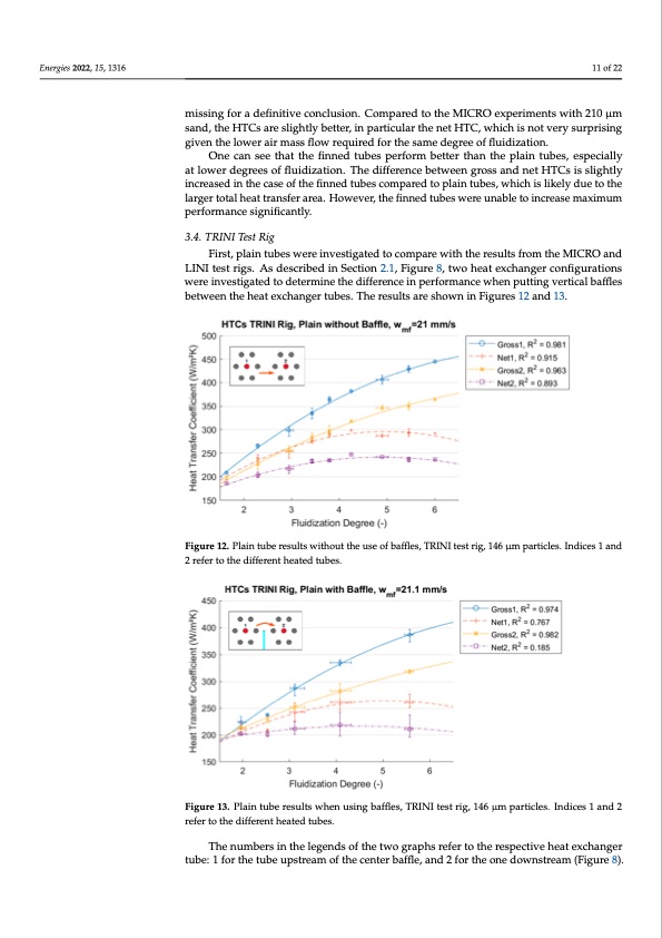
Energies 2022, 15, 1316 Figure 11. Results of the LINI test rig, plain and finned tubes, 146 μm particles. 11 of 22 The net HTC seems to decrease beyond a degree of fluidization of around 4 to 5, which is a good operational value, although measurements at higher degrees of missing for a definitive conclusion. Compared to the MICRO experiments with 210 μm fluidization are missing for a definitive conclusion. Compared to the MICRO experiments sand, the HTCs are slightly better, in particular the net HTC, which is not very surprising with 210 μm sand, the HTCs are slightly better, in particular the net HTC, which is not given the lower air mass flow required for the same degree of fluidization. very surprising given the lower air mass flow required for the same degree of fluidization. One can see that the finned tubes perform better than the plain tubes, especially One can see that the finned tubes perform better than the plain tubes, especially at at lower degrees of fluidization. The difference between gross and net HTCs is slightly lower degrees of fluidization. The difference between gross and net HTCs is slightly increased in the case of the finned tubes compared to plain tubes, which is likely due to the increased in the case of the finned tubes compared to plain tubes, which is likely due to larger total heat transfer area. However, the finned tubes were unable to increase maximum the larger total heat transfer area. However, the finned tubes were unable to increase performance significantly. maximum performance significantly. 3.4. TRINI Test Rig 3.4. TRINI Test Rig First, plain tubes were investigated to compare with the results from the MICRO and First, plain tubes were investigated to compare with the results from the MICRO and LINI test rigs. As described in Section 2.1, Figure 8, two heat exchanger configurations LINI test rigs. As described in Section 2.1, Figure 8, two heat exchanger configurations were investigated to determine the difference in performance when putting vertical baffles were investigated to determine the difference in performance when putting vertical between the heat exchanger tubes. The results are shown in Figures 12 and 13. baffles between the heat exchanger tubes. The results are shown in Figures 12 and 13. Figure 12. Plain tube results without the use of baffles, TRINI test rig, 146 μm particles. Indices 1 Energies 2022, 15, x FOR PEER REVIEWFigure 12. Plain tube results without the use of baffles, TRINI test rig, 146 μm particl1e2s.oIfn2d2ices 1 and and 2 refer to the different heated tubes. 2 refer to the different heated tubes. Figure 13. Plain tube results when using baffles, TRINI test rig, 146 μm particles. Indices 1 and 2 Figure 13. Plain tube results when using baffles, TRINI test rig, 146 μm particles. Indices 1 and 2 refer to the different heated tubes. refer to the different heated tubes. The numbers in the legends of the two graphs refer to the respective heat exchanger The numbers in the legends of the two graphs refer to the respective heat exchanger tube: 1 for the tube upstream of the center baffle, and 2 for the one downstream (Figure tube: 1 for the tube upstream of the center baffle, and 2 for the one downstream (Figure 8). 8). It is not entirely clear why the two tubes show significantly different values, while both their heat transfer behaviors seem qualitatively similar and consistent within themselves. The influence of the baffle could be an explanation in the case of those experiments that included it, but not for the ones that did not. It is possible that the local fluidization around the respective sensors was different or that the produced heat fromPDF Image | Heat Transfer between Finned Tubes
PDF Search Title:
Heat Transfer between Finned TubesOriginal File Name Searched:
energies-15-01316.pdfDIY PDF Search: Google It | Yahoo | Bing
Turbine and System Plans CAD CAM: Special for this month, any plans are $10,000 for complete Cad/Cam blueprints. License is for one build. Try before you buy a production license. More Info
Waste Heat Power Technology: Organic Rankine Cycle uses waste heat to make electricity, shaft horsepower and cooling. More Info
All Turbine and System Products: Infinity Turbine ORD systems, turbine generator sets, build plans and more to use your waste heat from 30C to 100C. More Info
CO2 Phase Change Demonstrator: CO2 goes supercritical at 30 C. This is a experimental platform which you can use to demonstrate phase change with low heat. Includes integration area for small CO2 turbine, static generator, and more. This can also be used for a GTL Gas to Liquids experimental platform. More Info
Introducing the Infinity Turbine Products Infinity Turbine develops and builds systems for making power from waste heat. It also is working on innovative strategies for storing, making, and deploying energy. More Info
Need Strategy? Use our Consulting and analyst services Infinity Turbine LLC is pleased to announce its consulting and analyst services. We have worked in the renewable energy industry as a researcher, developing sales and markets, along with may inventions and innovations. More Info
Made in USA with Global Energy Millennial Web Engine These pages were made with the Global Energy Web PDF Engine using Filemaker (Claris) software.
Sand Battery Sand and Paraffin for TES Thermo Energy Storage More Info
| CONTACT TEL: 608-238-6001 Email: greg@infinityturbine.com | RSS | AMP |