PDF Publication Title:
Text from PDF Page: 012
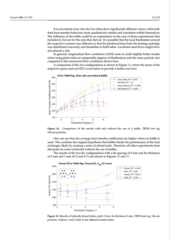
Energies 2022, 15, 1316 Figure 13. Plain tube results when using baffles, TRINI test rig, 146 μm particles. Indices 1 and 2 refer to the different heated tubes. 12 of 22 The numbers in the legends of the two graphs refer to the respective heat exchanger tube: 1 for the tube upstream of the center baffle, and 2 for the one downstream (Figure 8). It is not entirely clear why the two tubes show significantly different values, while both theirIthiseantotreantsirfelrybceleharvwiohrys tsheemtwqoutuablietsatsihvoewlysiigmnifliacranatnlyddcioffnesreisnttevnatlwueist,hwinhitlheemselves. both their heat transfer behaviors seem qualitatively similar and consistent within The influence of the baffle could be an explanation in the case of those experiments that themselves. The influence of the baffle could be an explanation in the case of those included it, but not for the ones that did not. It is possible that the local fluidization around experiments that included it, but not for the ones that did not. It is possible that the local the respective sensors was different or that the produced heat from the heating cartridge fluidization around the respective sensors was different or that the produced heat from was distributed unevenly and dissimilar in both tubes. Localized sand flows might have the heating cartridge was distributed unevenly and dissimilar in both tubes. Localized also played a role. sand flows might have also played a role. In general, longitudinal flow conditions (LINI) seem to yield slightly better results In general, longitudinal flow conditions (LINI) seem to yield slightly better results when using plain tubes at comparable degrees of fluidization and the same particle size when using plain tubes at comparable degrees of fluidization and the same particle size compared to the transversal flow conditions shown here. compared to the transversal flow conditions shown here. A comparison of the two configurations is shown in Figure 14, where the mean of the A comparison of the two configurations is shown in Figure 14, where the mean of the resspeecctitviveegrgorsossasnadnndetnHetTHCsTwCesrwetearkeetnatkoepnrotovipdreoavbidetetearboevtetrevrieowv.erview. Figure 14. Comparison of the results with and without the use of a baffle, TRINI test rig, 146 μm Figure 14. Comparison of the results with and without the use of a baffle, TRINI test rig, Energies 2022, 15, x FOR PEER REVIEW 13 of 22 particles. 146 μm particles. One can see that the average heat transfer coefficients are higher when no baffle is One can see that the average heat transfer coefficients are higher when no baffle is used. This confirms the original hypothesis that baffles hinder the performance of the heat used. This confirms the original hypothesis that baffles hinder the performance of the heat exchanger, likely by creating a series of stirred tanks. Therefore, all other experiments from exchanger, likely by creating a series of stirred tanks. Therefore, all other experiments this point on were conducted without the use of baffles. from this point on were conducted without the use of baffles. The results of the two fin configurations with a fin spacing of 9 mm and fin thickness The results of the two fin configurations with a fin spacing of 9 mm and fin thickness of 2 mm and 1 mm (9/2 and 9/1) are shown in Figures 15 and 16. of 2 mm and 1 mm (9/2 and 9/1) are shown in Figures 15 and 16. Figure 15. Results of helically finned tubes, pitch 9 mm, fin thickness 2 mm, TRINI test rig, 146 μm Figure 15. Results of helically finned tubes, pitch 9 mm, fin thickness 2 mm, TRINI test rig, 146 μm particles. Indices 1 and 2 refer to the different heated tubes. particles. Indices 1 and 2 refer to the different heated tubes.PDF Image | Heat Transfer between Finned Tubes
PDF Search Title:
Heat Transfer between Finned TubesOriginal File Name Searched:
energies-15-01316.pdfDIY PDF Search: Google It | Yahoo | Bing
Turbine and System Plans CAD CAM: Special for this month, any plans are $10,000 for complete Cad/Cam blueprints. License is for one build. Try before you buy a production license. More Info
Waste Heat Power Technology: Organic Rankine Cycle uses waste heat to make electricity, shaft horsepower and cooling. More Info
All Turbine and System Products: Infinity Turbine ORD systems, turbine generator sets, build plans and more to use your waste heat from 30C to 100C. More Info
CO2 Phase Change Demonstrator: CO2 goes supercritical at 30 C. This is a experimental platform which you can use to demonstrate phase change with low heat. Includes integration area for small CO2 turbine, static generator, and more. This can also be used for a GTL Gas to Liquids experimental platform. More Info
Introducing the Infinity Turbine Products Infinity Turbine develops and builds systems for making power from waste heat. It also is working on innovative strategies for storing, making, and deploying energy. More Info
Need Strategy? Use our Consulting and analyst services Infinity Turbine LLC is pleased to announce its consulting and analyst services. We have worked in the renewable energy industry as a researcher, developing sales and markets, along with may inventions and innovations. More Info
Made in USA with Global Energy Millennial Web Engine These pages were made with the Global Energy Web PDF Engine using Filemaker (Claris) software.
Sand Battery Sand and Paraffin for TES Thermo Energy Storage More Info
| CONTACT TEL: 608-238-6001 Email: greg@infinityturbine.com | RSS | AMP |