PDF Publication Title:
Text from PDF Page: 015
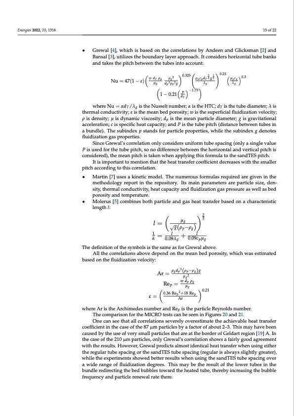
Energies 2022, 15, 1316 15 of 22 • Grewal [4], which is based on the correlations by Andeen and Glicksman [2] and Bansal [3], utilizes the boundary layer approach. It considers horizontal tube banks and takes the pitch between the tubes into account: Nu = 47(1 − ε) T 0.23 w d μg μg2 0.325 ρpcpd 32 g12 T μgcg 0.3 λg ρp based on the fluidization velocity: dp3ρp2g P −1.75 1 − 0.21 dT λg where Nu = αdT/λg is the Nusselt number; α is the HTC; dT is the tube diameter; λ is thermal conductivity; ε is the mean bed porosity; w is the superficial fluidization velocity; ρ is density; μ is dynamic viscosity; dp is the mean particle diameter; g is gravitational acceleration; c is specific heat capacity; and P is the tube pitch (distance between tubes in a bundle). The subindex p stands for particle properties, while the subindex g denotes fluidization gas properties. Since Grewal’s correlation only considers uniform tube spacing (only a single value P is used for the tube pitch, so no difference between the horizontal and vertical pitch is considered), the mean pitch is taken when applying this formula to the sandTES pitch. It is important to mention that the heat transfer coefficient decreases with the smaller pitch according to this correlation. • Martin [7] uses a kinetic model. The numerous formulas required are given in the methodology report in the repository. Its main parameters are particle size, den- sity, thermal conductivity, heat capacity and fluidization gas pressure as well as bed porosity and temperature. • Molerus [5] combines both particle and gas heat transfer based on a characteristic length l: μg 32 l = √g(ρp−ρg) 1=l+l α 0.09λg 0.09cpμg The definition of the symbols is the same as for Grewal above. All the correlations above depend on the mean bed porosity, which was estimated Ar = ρgdp3(ρp−ρg)g μg2 Rep = w dp ρg μg 0.36Rep2+18Rep 0.21 ε= Ar where Ar is the Archimedes number and Rep is the particle Reynolds number. The comparison for the MICRO tests can be seen in Figures 20 and 21. One can see that all correlations severely overestimate the achievable heat transfer coefficient in the case of the 87 μm particles by a factor of about 2–3. This may have been caused by the use of very small particles that are at the border of Geldart region [19] A. In the case of the 210 μm particles, only Grewal’s correlation shows a fairly good agreement with the results. However, Grewal predicts almost identical heat transfer when using either the regular tube spacing or the sandTES tube spacing (regular is always slightly greater), while the experiments showed better results when using the sandTES tube spacing over a wide range of fluidization degrees. This may be the result of the lower tubes in the bundle redirecting the bed bubbles toward the heated tube, thereby increasing the bubble frequency and particle renewal rate there.PDF Image | Heat Transfer between Finned Tubes

PDF Search Title:
Heat Transfer between Finned TubesOriginal File Name Searched:
energies-15-01316.pdfDIY PDF Search: Google It | Yahoo | Bing
Turbine and System Plans CAD CAM: Special for this month, any plans are $10,000 for complete Cad/Cam blueprints. License is for one build. Try before you buy a production license. More Info
Waste Heat Power Technology: Organic Rankine Cycle uses waste heat to make electricity, shaft horsepower and cooling. More Info
All Turbine and System Products: Infinity Turbine ORD systems, turbine generator sets, build plans and more to use your waste heat from 30C to 100C. More Info
CO2 Phase Change Demonstrator: CO2 goes supercritical at 30 C. This is a experimental platform which you can use to demonstrate phase change with low heat. Includes integration area for small CO2 turbine, static generator, and more. This can also be used for a GTL Gas to Liquids experimental platform. More Info
Introducing the Infinity Turbine Products Infinity Turbine develops and builds systems for making power from waste heat. It also is working on innovative strategies for storing, making, and deploying energy. More Info
Need Strategy? Use our Consulting and analyst services Infinity Turbine LLC is pleased to announce its consulting and analyst services. We have worked in the renewable energy industry as a researcher, developing sales and markets, along with may inventions and innovations. More Info
Made in USA with Global Energy Millennial Web Engine These pages were made with the Global Energy Web PDF Engine using Filemaker (Claris) software.
Sand Battery Sand and Paraffin for TES Thermo Energy Storage More Info
| CONTACT TEL: 608-238-6001 Email: greg@infinityturbine.com | RSS | AMP |