PDF Publication Title:
Text from PDF Page: 017
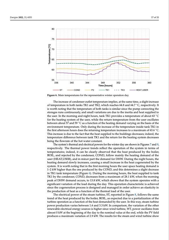
Energies 2022, 15, 6331 4.1. Daily Results for a Winter Day The selected winter operation day is the 15 of January (between 336 and 360 year). The main temperatures for the selected day are reported in Figure 6. performance is reported through yearly data. of temperature in both tanks TK1 and TK2, which reaches 64.8 and 64.7 ◦C, respectively. It The operation of the steam turbine, ST, is characterized by a stable outlet tem is worth noting that the temperature of both tanks is similar since the pump connecting the of 75 °C during the day, due to a constant expansion pressure at its outlet and to storages runs continuously, and small variations are due to the inertia and heat supplied to trol of the temperature exiting the boiler, BOIL, (220 °C), as planned by the de the user. In the morning and night hours, tank TK1 provides a temperature of about 63 ◦C for the heating system of the user, while the return temperature from the user oscillates 17 of 33 80 75 70 65 60 55 336 340 ST 344 348 352 Time [hours] TK1 356 360 HEAT,USER COND P2 TK3 Figure 6. Main temperatures for the representative winter operation day. Figure 6. Main temperatures for the representative winter operation day. The increase of condenser outlet temperature implies, at the same time, a slight increase control strategy. These conditions allow one to also keep a stable temperature of t between about 57 and 59 ◦C as a function of the heating demand varying on the basis of the ing water exiting the condenser, COND, at 65 °C for almost the whole day, allo environment temperature. Only during the increase of the temperature inside tank TK1 in this time, to match the heating demand of the user. The temperature increases a the first afternoon hours does the returning temperature increases to a maximum of 63.6 ◦C. set point value in the period after noon since the produced heat cannot be fully This increase is due to the fact that the heat supplied to the buildings decreases; indeed, the bteymtphereatsuyrsetdeimffe.reDnecespbeitweetehnistasniktuTaKt1ioand,theretuisrnnforntheecheesastiitnygtsoysatecmtivdaectreeatsheesauxili being the flowrate of the hot water constant. exchanger to limit the temperature of cooling entering the condenser, since it kee The system’s thermal and electrical powers for the winter day are shown in Figures 7 and 8, 65 °C as shown by the trend of pump P2’s outlet temperature. During the selec respectively. The thermal power trends reflect the operation of the system in terms of the inlet temperature to condenser, COND, oscillates between 59.7 and 63.6 °C en temperatures; indeed, it can be clearly observed that the heat produced by the boiler, pBOroILp,earnodprerjeactieodnboy fththe ecocnodnednseenr,sCinOgNpDr,ofcoellsoswamndainolfytthe whehatoinleg sdtemamandcyocf lteh.e user (HEAT,USER), and in minor part the demand for DHW. During the night hours, the The increase of condenser outlet temperature implies, at the same time, a s heating demand slowly increases, causing a small increase in the heat cogenerated by the crease of temperature in both tanks TK1 and TK2, which reaches 64.8 and 64.7 °C, system. It is worth noting that in the first morning hours the user space heating demand is tively. It is worth noting that the temperature of both tanks is similar since the pu 1–2 kW higher than the one produced by the COND, and this determines a slight decrease necting the storages runs continuously, and small variations are due to the ine in TK1 tank temperature (Figure 6). During the morning hours, the heat supplied to tank hTKea1tbsyuthpepcloiendetnosetrh,eCOuNseDr,.dInecrtehaesemsforormninagmaxnidmunmigohft2h8.o1ukrWs,wtahnekntThKem1oprrnoinvgides a t peak of DHW demand occurs, to 13.8 kW, which shows that the system operates with a ture of about 63 °C for the heating system of the user, while the return temperat significant variation of the load during the day. This operation characteristic is achieved the user oscillates between about 57 and 59 °C as a function of the heating demand since the cogeneration process is designed and managed in order achieve an elasticity in on the basis of the environment temperature. Only during the increase of the tem the production of heat as a function of the thermal load of the user. insidTehetaenlekctTricKa1l pionwtehreofitrhset satfetaemrntuorobninhe,oSuTr, sredporetsedthine Friegturren8i,nfoglltoewms ptheerasatmuree incre trend of the heat produced by the boiler, BOIL, as expected due to a partialization of the maximum of 63.6 °C. This increase is due to the fact that the heat supplied to the b turbine operation as a function of the heat demanded by the user. In this way, steam turbine decreases; indeed, the temperature difference between tank TK1 and the retur power production varies between 1.6 and 3.3 kW. In comparison, the variation of the other heating system decreases being the flowrate of the hot water constant. renewable electrical energy sources is higher since wind turbine, WT, power oscillates from The system’s thermal and electrical powers for the winter day are shown in almost 0 kW at the beginning of the day to the nominal value at the end, while the PV field 7praondudc8es, raemspaxeicmtiuvmelvya.rTiahtioenthofe2r.m9 kaWl p. Tohwe erersturletsnfdorstrhefsletecatmthaendopweinrdattiuornbionef tshoewsystem of temperatures; indeed, it can be clearly observed that the heat produced by th Temperatures [°C] p t v w b a p t s l m r e u p a u n i ePDF Image | Hybrid Polygeneration System Based on Biomass Wind and Solar Energy
PDF Search Title:
Hybrid Polygeneration System Based on Biomass Wind and Solar EnergyOriginal File Name Searched:
energies-15-06331-v2.pdfDIY PDF Search: Google It | Yahoo | Bing
Turbine and System Plans CAD CAM: Special for this month, any plans are $10,000 for complete Cad/Cam blueprints. License is for one build. Try before you buy a production license. More Info
Waste Heat Power Technology: Organic Rankine Cycle uses waste heat to make electricity, shaft horsepower and cooling. More Info
All Turbine and System Products: Infinity Turbine ORD systems, turbine generator sets, build plans and more to use your waste heat from 30C to 100C. More Info
CO2 Phase Change Demonstrator: CO2 goes supercritical at 30 C. This is a experimental platform which you can use to demonstrate phase change with low heat. Includes integration area for small CO2 turbine, static generator, and more. This can also be used for a GTL Gas to Liquids experimental platform. More Info
Introducing the Infinity Turbine Products Infinity Turbine develops and builds systems for making power from waste heat. It also is working on innovative strategies for storing, making, and deploying energy. More Info
Need Strategy? Use our Consulting and analyst services Infinity Turbine LLC is pleased to announce its consulting and analyst services. We have worked in the renewable energy industry as a researcher, developing sales and markets, along with may inventions and innovations. More Info
Made in USA with Global Energy Millennial Web Engine These pages were made with the Global Energy Web PDF Engine using Filemaker (Claris) software.
Sand Battery Sand and Paraffin for TES Thermo Energy Storage More Info
| CONTACT TEL: 608-238-6001 Email: greg@infinityturbine.com | RSS | AMP |