PDF Publication Title:
Text from PDF Page: 014
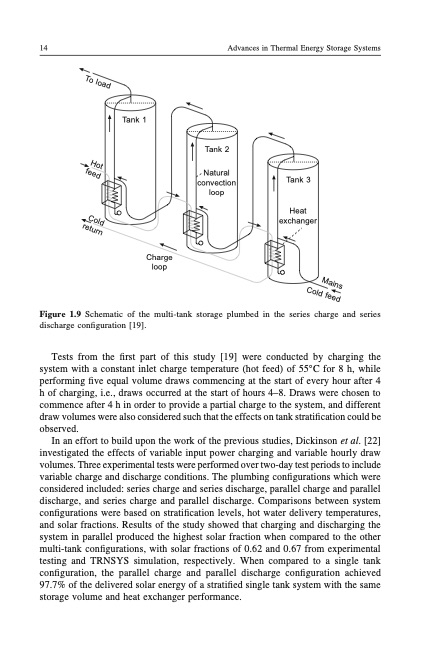
14 Advances in Thermal Energy Storage Systems Tank 1 Tank 2 Natural convection loop Tank 3 Heat exchanger Charge loop Figure 1.9 Schematic of the multi-tank storage plumbed in the series charge and series discharge configuration [19]. Tests from the first part of this study [19] were conducted by charging the system with a constant inlet charge temperature (hot feed) of 55°C for 8 h, while performing five equal volume draws commencing at the start of every hour after 4 h of charging, i.e., draws occurred at the start of hours 4–8. Draws were chosen to commence after 4 h in order to provide a partial charge to the system, and different draw volumes were also considered such that the effects on tank stratification could be observed. In an effort to build upon the work of the previous studies, Dickinson et al. [22] investigated the effects of variable input power charging and variable hourly draw volumes. Three experimental tests were performed over two-day test periods to include variable charge and discharge conditions. The plumbing configurations which were considered included: series charge and series discharge, parallel charge and parallel discharge, and series charge and parallel discharge. Comparisons between system configurations were based on stratification levels, hot water delivery temperatures, and solar fractions. Results of the study showed that charging and discharging the system in parallel produced the highest solar fraction when compared to the other multi-tank configurations, with solar fractions of 0.62 and 0.67 from experimental testing and TRNSYS simulation, respectively. When compared to a single tank configuration, the parallel charge and parallel discharge configuration achieved 97.7% of the delivered solar energy of a stratified single tank system with the same storage volume and heat exchanger performance. To load Hot feed Cold return Mains Cold feedPDF Image | Introduction to thermal energy storage TES systems
PDF Search Title:
Introduction to thermal energy storage TES systemsOriginal File Name Searched:
TES-introduction.pdfDIY PDF Search: Google It | Yahoo | Bing
Turbine and System Plans CAD CAM: Special for this month, any plans are $10,000 for complete Cad/Cam blueprints. License is for one build. Try before you buy a production license. More Info
Waste Heat Power Technology: Organic Rankine Cycle uses waste heat to make electricity, shaft horsepower and cooling. More Info
All Turbine and System Products: Infinity Turbine ORD systems, turbine generator sets, build plans and more to use your waste heat from 30C to 100C. More Info
CO2 Phase Change Demonstrator: CO2 goes supercritical at 30 C. This is a experimental platform which you can use to demonstrate phase change with low heat. Includes integration area for small CO2 turbine, static generator, and more. This can also be used for a GTL Gas to Liquids experimental platform. More Info
Introducing the Infinity Turbine Products Infinity Turbine develops and builds systems for making power from waste heat. It also is working on innovative strategies for storing, making, and deploying energy. More Info
Need Strategy? Use our Consulting and analyst services Infinity Turbine LLC is pleased to announce its consulting and analyst services. We have worked in the renewable energy industry as a researcher, developing sales and markets, along with may inventions and innovations. More Info
Made in USA with Global Energy Millennial Web Engine These pages were made with the Global Energy Web PDF Engine using Filemaker (Claris) software.
Sand Battery Sand and Paraffin for TES Thermo Energy Storage More Info
| CONTACT TEL: 608-238-6001 Email: greg@infinityturbine.com | RSS | AMP |