PDF Publication Title:
Text from PDF Page: 007
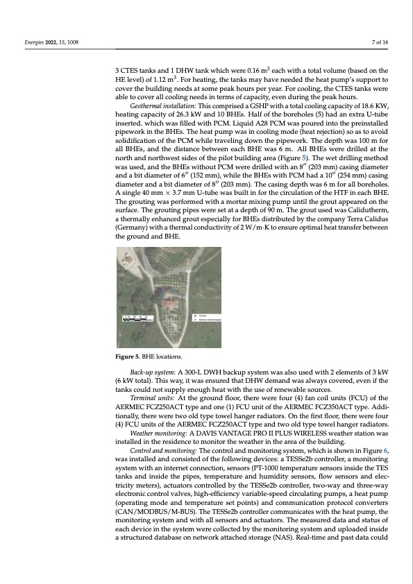
Energies 2022, 15, 1008 7 of 16 3 CTES tanks and 1 DHW tank which were 0.16 m3 each with a total volume (based on the 248 Figure 4. Solar collectors on the roof. 249 HE level) of 1.12 m3. For heating, the tanks may have needed the heat pump’s support to cover the building needs at some peak hours per year. For cooling, the CTES tanks were able to cover all cooling needs in terms of capacity, even during the peak hours. Geothermal installation: This comprised a GSHP with a total cooling capacity of 18.6 250 Geothermal installation: This comprised a GSHP with a total cooling capacity of 18.6 KW, KW, heating capacity of 26.3 kW and 10 BHEs. Half of the boreholes (5) had an extra U- 251 heating capacity of 26.3 kW and 10 BHEs. Half of the boreholes (5) had an extra U-tube tube inserted. which was filled with PCM. Liquid A28 PCM was poured into the prein- 252 inserted. which was filled with PCM. Liquid A28 PCM was poured into the preinstalled stalled pipework in the BHEs. The heat pump was in cooling mode (heat rejection) so as 253 pipework in the BHEs. The heat pump was in cooling mode (heat rejection) so as to avoid to avoid solidification of the PCM while traveling down the pipework. The depth was 100 254 solidification of the PCM while traveling down the pipework. The depth was 100 m for m for all BHEs, and the distance between each BHE was 6 m. All BHEs were drilled at the 255 all BHEs, and the distance between each BHE was 6 m. All BHEs were drilled at the north and northwest sides of the pilot building area (Figure 5). The wet drilling method 256 north and northwest sides of the pilot building area (Figure 5). The wet drilling method wasused,andtheBHEswithoutPCMweredrilledwithan8′′"(203mm)casingdiameter 257 was used, and the BHEs without PCM were drilled with an 8 (203 mm) casing diameter andabitdiameterof6′′"(152mm),whiletheBHEswithPCMhada10′′"(254mm)casing 258 and a bit diameter of 6 (152 mm), while the BHEs with PCM had a 10 (254 mm) casing diameter and a bit diameter of 8"′′(203 mm). The casing depth was 6 m for all boreholes. A 259 diameter and a bit diameter of 8 (203 mm). The casing depth was 6 m for all boreholes. single 40 mm × 3.7 mm U-tube was built in for the circulation of the HTF in each BHE. The 260 A single 40 mm × 3.7 mm U-tube was built in for the circulation of the HTF in each BHE. grouting was performed with a mortar mixing pump until the grout appeared on the sur- 261 The grouting was performed with a mortar mixing pump until the grout appeared on the face. The grouting pipes were set at a depth of 90 m. The grout used was Calidutherm, a 262 surface. The grouting pipes were set at a depth of 90 m. The grout used was Calidutherm, thermally enhanced grout especially for BHEs distributed by the company Terra Calidus 263 a thermally enhanced grout especially for BHEs distributed by the company Terra Calidus (Germany) with a thermal conductivity of 2 W/m·K to ensure optimal heat transfer be- 264 (Germany) with a thermal conductivity of 2 W/m·K to ensure optimal heat transfer between tween the ground and BHE. 265 the ground and BHE. 266 Figure 5. BHE locations. 267 Figure 5. BHE locations. Back-up system: A 300-L DWH backup system was also used with 2 elements of 3 kW Back-up system: A 300-L DWH backup system was also used with 2 elements of 3 kW 268 (6 kW total). This way, it was ensured that DHW demand was always covered, even if the (6 kW total). This way, it was ensured that DHW demand was always covered, even if the 269 tanks could not supply enough heat with the use of renewable sources. tanks could not supply enough heat with the use of renewable sources. 270 Terminal units: At the ground floor, there were four (4) fan coil units (FCU) of the Terminal units: At the ground floor, there were four (4) fan coil units (FCU) of the 271 AERMEC FCZ250ACT type and one (1) FCU unit of the AERMEC FCZ350ACT type. Addi- AERMEC FCZ250ACT type and one (1) FCU unit of the AERMEC FCZ350ACT type. Ad- 272 tionally, there were two old type towel hanger radiators. On the first floor, there were four ditionally, there were two old type towel hanger radiators. On the first floor, there were 273 (4) FCU units of the AERMEC FCZ250ACT type and two old type towel hanger radiators. four (4) FCU units of the AERMEC FCZ250ACT type and two old type towel hanger ra- 274 Weather monitoring: A DAVIS VANTAGE PRO II PLUS WIRELESS weather station was diators. 275 installed in the residence to monitor the weather in the area of the building. Weather monitoring: A DAVIS VANTAGE PRO II PLUS WIRELESS weather station 276 Control and monitoring: The control and monitoring system, which is shown in Figure 6, was installed in the residence to monitor the weather in the area of the building. 277 was installed and consisted of the following devices: a TESSe2b controller, a monitoring Control and monitoring: The control and monitoring system, which is shown in Figure 278 system with an internet connection, sensors (PT-1000 temperature sensors inside the TES 6, was installed and consisted of the following devices: a TESSe2b controller, a monitoring 279 tanks and inside the pipes, temperature and humidity sensors, flow sensors and elec- tricity meters), actuators controlled by the TESSe2b controller, two-way and three-way electronic control valves, high-efficiency variable-speed circulating pumps, a heat pump (operating mode and temperature set points) and communication protocol converters (CAN/MODBUS/M-BUS). The TESSe2b controller communicates with the heat pump, the monitoring system and with all sensors and actuators. The measured data and status of each device in the system were collected by the monitoring system and uploaded inside a structured database on network attached storage (NAS). Real-time and past data couldPDF Image | Latent Thermal Energy Storage Application
PDF Search Title:
Latent Thermal Energy Storage ApplicationOriginal File Name Searched:
energies-15-01008-v2.pdfDIY PDF Search: Google It | Yahoo | Bing
Turbine and System Plans CAD CAM: Special for this month, any plans are $10,000 for complete Cad/Cam blueprints. License is for one build. Try before you buy a production license. More Info
Waste Heat Power Technology: Organic Rankine Cycle uses waste heat to make electricity, shaft horsepower and cooling. More Info
All Turbine and System Products: Infinity Turbine ORD systems, turbine generator sets, build plans and more to use your waste heat from 30C to 100C. More Info
CO2 Phase Change Demonstrator: CO2 goes supercritical at 30 C. This is a experimental platform which you can use to demonstrate phase change with low heat. Includes integration area for small CO2 turbine, static generator, and more. This can also be used for a GTL Gas to Liquids experimental platform. More Info
Introducing the Infinity Turbine Products Infinity Turbine develops and builds systems for making power from waste heat. It also is working on innovative strategies for storing, making, and deploying energy. More Info
Need Strategy? Use our Consulting and analyst services Infinity Turbine LLC is pleased to announce its consulting and analyst services. We have worked in the renewable energy industry as a researcher, developing sales and markets, along with may inventions and innovations. More Info
Made in USA with Global Energy Millennial Web Engine These pages were made with the Global Energy Web PDF Engine using Filemaker (Claris) software.
Sand Battery Sand and Paraffin for TES Thermo Energy Storage More Info
| CONTACT TEL: 608-238-6001 Email: greg@infinityturbine.com | RSS | AMP |