PDF Publication Title:
Text from PDF Page: 009
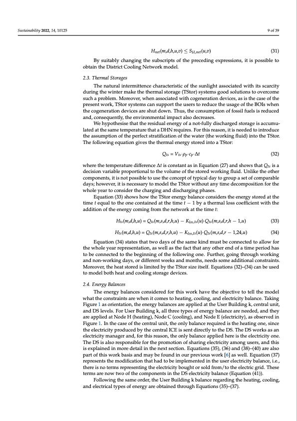
Sustainability 2022, 14, 10125 9 of 39 Hnet(m,d,h,u,v) ≤ SH,net(u,v) (31) By suitably changing the subscripts of the preceding expressions, it is possible to obtain the District Cooling Network model. 2.3. Thermal Storages The natural intermittence characteristic of the sunlight associated with its scarcity during the winter make the thermal storage (TStor) systems good solutions to overcome such a problem. Moreover, when associated with cogeneration devices, as is the case of the present work, TStor systems can support the users to reduce the usage of the BOIs when the cogeneration devices are shut down. Thus, the consumption of fossil fuels is reduced and, consequently, the environmental impact also decreases. We hypothesise that the residual energy of a not-fully discharged storage is accumu- lated at the same temperature that a DHN requires. For this reason, it is needed to introduce the assumption of the perfect stratification of the water (the working fluid) into the TStor. The following equation gives the thermal energy stored into a TStor: Qts = Vts·ρp·cp·∆t (32) where the temperature difference ∆t is constant as in Equation (27) and shows that Qts is a decision variable proportional to the volume of the stored working fluid. Unlike the other components, it is not possible to use the concept of typical day to group a set of comparable days; however, it is necessary to model the TStor without any time decomposition for the whole year to consider the charging and discharging phases. Equation (33) shows how the TStor energy balance considers the energy stored at the time t equal to the one contained at the time t − 1 by a thermal loss coefficient with the addition of the energy coming from the network at the time t: Hts(m,d,h,u) = Qts(m,s,d,r,h,u) − Klos,ts(u)·Qts(m,s,d,r,h − 1,u) (33) Hts(m,d,h,u) = Qts(m,s,d,r,h,u) − Klos,ts(u)·Qts(m,s,d,r − 1,24,u) (34) Equation (34) states that two days of the same kind must be connected to allow for the whole year representation, as well as the fact that any other end of a time period has to be connected to the beginning of the following one. Further, going through working and non-working days, or different weeks and months, needs some additional constraints. Moreover, the heat stored is limited by the TStor size itself. Equations (32)–(34) can be used to model both heat and cooling storage devices. 2.4. Energy Balances The energy balances considered for this work have the objective to tell the model what the constraints are when it comes to heating, cooling, and electricity balance. Taking Figure 1 as orientation, the energy balances are applied at the User Building k, central unit, and DS levels. For User Building k, all three types of energy balance are needed, and they are applied at Node H (heating), Node C (cooling), and Node E (electricity), as observed in Figure 1. In the case of the central unit, the only balance required is the heating one, since the electricity produced by the central ICE is sent directly to the DS. The DS works as an electricity manager and, for this reason, the only balance applied here is the electricity one. The DS is also responsible for the promotion of sharing electricity among users, and this is explained in more detail in the next section. Equations (35), (36) and (38)–(40) are also part of this work basis and may be found in our previous work [6] as well. Equation (37) represents the modification that had to be implemented in the user electricity balance, i.e., there is no terms representing the electricity bought or sold from/to the electric grid. These terms are now two of the components in the DS electricity balance (Equation (41)). Following the same order, the User Building k balance regarding the heating, cooling, and electrical types of energy are obtained through Equations (35)–(37).PDF Image | Optimal Sharing Electricity and Thermal Energy

PDF Search Title:
Optimal Sharing Electricity and Thermal EnergyOriginal File Name Searched:
sustainability-14-10125-v2.pdfDIY PDF Search: Google It | Yahoo | Bing
Turbine and System Plans CAD CAM: Special for this month, any plans are $10,000 for complete Cad/Cam blueprints. License is for one build. Try before you buy a production license. More Info
Waste Heat Power Technology: Organic Rankine Cycle uses waste heat to make electricity, shaft horsepower and cooling. More Info
All Turbine and System Products: Infinity Turbine ORD systems, turbine generator sets, build plans and more to use your waste heat from 30C to 100C. More Info
CO2 Phase Change Demonstrator: CO2 goes supercritical at 30 C. This is a experimental platform which you can use to demonstrate phase change with low heat. Includes integration area for small CO2 turbine, static generator, and more. This can also be used for a GTL Gas to Liquids experimental platform. More Info
Introducing the Infinity Turbine Products Infinity Turbine develops and builds systems for making power from waste heat. It also is working on innovative strategies for storing, making, and deploying energy. More Info
Need Strategy? Use our Consulting and analyst services Infinity Turbine LLC is pleased to announce its consulting and analyst services. We have worked in the renewable energy industry as a researcher, developing sales and markets, along with may inventions and innovations. More Info
Made in USA with Global Energy Millennial Web Engine These pages were made with the Global Energy Web PDF Engine using Filemaker (Claris) software.
Sand Battery Sand and Paraffin for TES Thermo Energy Storage More Info
| CONTACT TEL: 608-238-6001 Email: greg@infinityturbine.com | RSS | AMP |