PDF Publication Title:
Text from PDF Page: 011
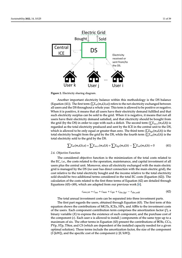
Sustainability 2022, 14, 10125 Sustainability 2022, 14, 10125 11 of 39 Figure 2. Electricity sharing diagram. Figure 2. Electricity sharing diagram. 2.6. OAbnjeoctihverFiumncptoiorntant electricity balance within this methodology is the DS balance (Equation (41)). The first term (∑Eut(m,d,h,u)) refers to the net electricity exchanged between The considered objective function is the minimization of the total costs related to the all users and the DS throughout a whole year. This term is allowed to be positive or negative. EC, i.e., the costs related to the operation, maintenance, and capital investment of all users 12 of 41 When it is positive, it means that all users have their electricity demand fulfilled and that plus the central unit. Moreover, since all electricity exchanged with the main electric grid such electricity surplus can be sold to the grid. When it is negative, it means that not all is managed by the DS (no user has direct connection with the main electric grid), the cost users have their electricity demand satisfied, and that electricity should be bought from relative to the total electricity bought and the income relative to the total electricity sold the grid (by the DS) in order to cope with such a deficit. The second term (∑Eice,c(m,d,h)) is should be two additional terms considered in the total EC costs (Equation (42)). The cal- regarded as the total electricity produced and sent by the ICE in the central unit to the DS, culation of the costs related to the first three terms of Equation (42) are detailed through which is allowed to be only equal or greater than zero. The third term (∑Ebgt(m,d,h)) is the Equations (43)–(49), which are adapted from our previous work [6]. total electricity bought from the grid by the DS, while the fourth term (∑Esel(m,d,h)) is the total electricity sold to the grcidannb,toyt =thceinvD+Sc.man + cope + celec,bgt − relec,sold (42) The total annual investment costs can be separated into three investment parts. ∑Eut(m,d,h,u) + ∑Eice,c(m,d,h) + ∑Ebgt(m,d,h) − ∑Esel(m,d,h) = 0 (41) The first part regards the users, obtained through Equation (43). The first term of this equation shows the contributions of MGTs, ICEs, HPs, and ABSs to the investment costs 2.6. Objective Function of the users. Each component contribution term comprises the amortization factor (f), a The considered objective function is the minimization of the total costs related to binary variable (X) to express the existence of such component, and the purchase cost of the EC, i.e., the costs related to the operation, maintenance, and capital investment of all the component (c). Each user u is allowed to install j components of the same type up to a users plus the central unit. Moreover, since all electricity exchanged with the main electric maximum of six. The other terms in Equation (43) present the contributions of BOIs, CCs, grid is managed by the DS (no user has direct connection with the main electric grid), the PVp, STp, TStor, and CS (which are dependent of the installed capacity needed for a given cost relative to the total electricity bought and the income relative to the total electricity optimal solution). These terms include the amortization factor, the size of the component sold should be two additional terms considered in the total EC costs (Equation (42)). The (S [kW]), and the specific cost of the component (c [€/kW]). calculation of the costs related to the first three terms of Equation (42) are detailed through The second part concerns the investments in the central unit (Equation (44)). As ob- Equations (43)–(49), which are adapted from our previous work [6]. served, this equation includes the variable and fixed costs related to the ICE, BOI, and DHN of the central unit, as well as the investment costs associated to STp and TStor. cann,tot = cinv + cman + cope + celec,bgt − relec,sold (42) The third part is concerned with the investment costs of the DHCN pipeline network (EquaTthioento(4ta5l))a.nTnhuisaelqinuvaetsiotmneconmtcporsitsecsatnhebfeixsedpacroastesd(rienltaotetdhrteoethinevexsitsmteenctepoarratsb.sence The first part regards the users, obtained through Equation (43). The first term of this of a given pipeline connection) and the variable costs (related to the actual size of each equation shows the contributions of MGTs, ICEs, HPs, and ABSs to the investment costs pipeline connection and whether it is for heating or cooling). of the users. Each component contribution term comprises the amortization factor (f ), a cinv,u(u) = ∑j [fmgt Xmgt(j,u)·cmgt(j,u) + fice·Xice(j,u)·cice(j,u) + fhp·Xhp(j,u)·chp(j,u) + binary variable (X) to express the existence of such component, and the purchase cost of fabs·Xabs(j,u)·cabs(j,u)] + fboi·Sboi(u)·cboi+ fcc·Scc(u)·ccc + fpvp·Spvp(u)·cpvp + fstp·Sstp(u)·cstp + (43) the component (c). Each user u is allowed to install j components of the same type up to a fts·Sts(u)·cts + fts·Scs(u)·cts maximum of six. The other terms in Equation (43) present the contributions of BOIs, CCs, PVp, STp, TStor, and CS (which are dependent of the installed capacity needed for a given cinv,c = fice (Sice,c·cice,v + Xice,c·cice,f) + fboi ·(Sboi,c·cboi,v + Xboi,c·cboi,f) + fstp·Sstp,c·cstp,c + fts Sts,c optimal solution). These terms include the amortization factor, the size of the component (S [kW]), and the specific cost·cotfs,ct+hefnceto·(mcnpeto,f,cn·Xenett,(c c+[c€n/et,kv,Wc ·S])H.,net,c) (44)PDF Image | Optimal Sharing Electricity and Thermal Energy
PDF Search Title:
Optimal Sharing Electricity and Thermal EnergyOriginal File Name Searched:
sustainability-14-10125-v2.pdfDIY PDF Search: Google It | Yahoo | Bing
Turbine and System Plans CAD CAM: Special for this month, any plans are $10,000 for complete Cad/Cam blueprints. License is for one build. Try before you buy a production license. More Info
Waste Heat Power Technology: Organic Rankine Cycle uses waste heat to make electricity, shaft horsepower and cooling. More Info
All Turbine and System Products: Infinity Turbine ORD systems, turbine generator sets, build plans and more to use your waste heat from 30C to 100C. More Info
CO2 Phase Change Demonstrator: CO2 goes supercritical at 30 C. This is a experimental platform which you can use to demonstrate phase change with low heat. Includes integration area for small CO2 turbine, static generator, and more. This can also be used for a GTL Gas to Liquids experimental platform. More Info
Introducing the Infinity Turbine Products Infinity Turbine develops and builds systems for making power from waste heat. It also is working on innovative strategies for storing, making, and deploying energy. More Info
Need Strategy? Use our Consulting and analyst services Infinity Turbine LLC is pleased to announce its consulting and analyst services. We have worked in the renewable energy industry as a researcher, developing sales and markets, along with may inventions and innovations. More Info
Made in USA with Global Energy Millennial Web Engine These pages were made with the Global Energy Web PDF Engine using Filemaker (Claris) software.
Sand Battery Sand and Paraffin for TES Thermo Energy Storage More Info
| CONTACT TEL: 608-238-6001 Email: greg@infinityturbine.com | RSS | AMP |