PDF Publication Title:
Text from PDF Page: 008
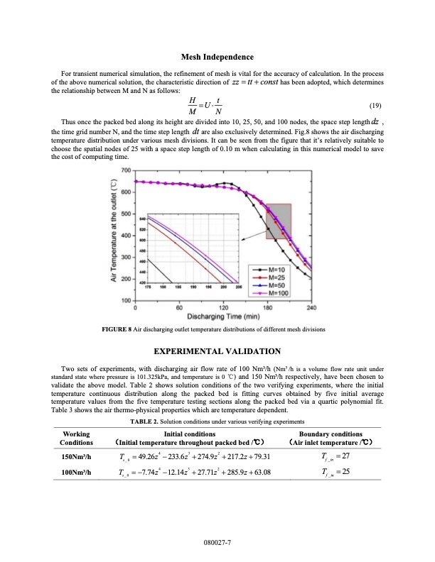
Mesh Independence For transient numerical simulation, the refinement of mesh is vital for the accuracy of calculation. In the process of the above numerical solution, the characteristic direction of zz tt const has been adopted, which determines the relationship between M and N as follows: H U t (19) MN Thus once the packed bed along its height are divided into 10, 25, 50, and 100 nodes, the space step length dz , the time grid number N, and the time step length dt are also exclusively determined. Fig.8 shows the air discharging temperature distribution under various mesh divisions. It can be seen from the figure that it’s relatively suitable to choose the spatial nodes of 25 with a space step length of 0.10 m when calculating in this numerical model to save the cost of computing time. FIGURE 8 Air discharging outlet temperature distributions of different mesh divisions EXPERIMENTAL VALIDATION Two sets of experiments, with discharging air flow rate of 100 Nm3/h (Nm3/h is a volume flow rate unit under standard state where pressure is 101.325kPa, and temperature is 0 °C) and 150 Nm3/h respectively, have been chosen to validate the above model. Table 2 shows solution conditions of the two verifying experiments, where the initial temperature continuous distribution along the packed bed is fitting curves obtained by five initial average temperature values from the five temperature testing sections along the packed bed via a quartic polynomial fit. Table 3 shows the air thermo-physical properties which are temperature dependent. TABLE 2. Solution conditions under various verifying experiments Working Conditions 150Nm3/h 100Nm3/h Initial conditions (Initial temperature throughout packed bed /°C) Boundary conditions (Air inlet temperature /°C) T 27 f _in T 25 f _in T s_0 T s_0 49.26z4 233.6z3 274.9z2 217.2z 79.31 7.74z4 12.14z3 27.71z2 285.9z 63.08 080027-7PDF Image | packed-bed thermal energy storage device
PDF Search Title:
packed-bed thermal energy storage deviceOriginal File Name Searched:
packed-bed-tes.pdfDIY PDF Search: Google It | Yahoo | Bing
Turbine and System Plans CAD CAM: Special for this month, any plans are $10,000 for complete Cad/Cam blueprints. License is for one build. Try before you buy a production license. More Info
Waste Heat Power Technology: Organic Rankine Cycle uses waste heat to make electricity, shaft horsepower and cooling. More Info
All Turbine and System Products: Infinity Turbine ORD systems, turbine generator sets, build plans and more to use your waste heat from 30C to 100C. More Info
CO2 Phase Change Demonstrator: CO2 goes supercritical at 30 C. This is a experimental platform which you can use to demonstrate phase change with low heat. Includes integration area for small CO2 turbine, static generator, and more. This can also be used for a GTL Gas to Liquids experimental platform. More Info
Introducing the Infinity Turbine Products Infinity Turbine develops and builds systems for making power from waste heat. It also is working on innovative strategies for storing, making, and deploying energy. More Info
Need Strategy? Use our Consulting and analyst services Infinity Turbine LLC is pleased to announce its consulting and analyst services. We have worked in the renewable energy industry as a researcher, developing sales and markets, along with may inventions and innovations. More Info
Made in USA with Global Energy Millennial Web Engine These pages were made with the Global Energy Web PDF Engine using Filemaker (Claris) software.
Sand Battery Sand and Paraffin for TES Thermo Energy Storage More Info
| CONTACT TEL: 608-238-6001 Email: greg@infinityturbine.com | RSS | AMP |