PDF Publication Title:
Text from PDF Page: 007
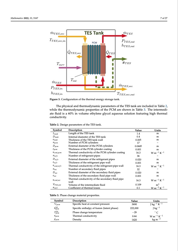
Mathematics 2022, 10, 3167 7 of 27 m ̇ T ES,sec TT ES,sec,in Tsurr Tint TES Tank PCM m ̇ T ES PT ES,out hT ES,out xTES m ̇ T E S , s e c TT ES,sec,out Q ̇ T ES,sec Q ̇ T ES m ̇ T E S PT ES,in hT ES,in Figure 3. Configuration of the thermal energy storage tank. The physical and thermodynamic parameters of the TES tank are included in Table 2, while the thermodynamic properties of the PCM are shown in Table 3. The intermedi- ate fluid is a 60% in volume ethylene glycol aqueous solution featuring high thermal conductivity. Table 2. Design parameters of the TES tank. Symbol Ltank Dtank etank npcm Dpcm epcm κcoat,pcm nrefr Drefr erefr κcoat,re f r nsec Dsec esec κcoat,sec VTES,int αsurr Description Length of the TES tank Internal diameter of the TES tank Thickness of the TES tank wall Number of PCM cylinders External diameter of the PCM cylinders Thickness of the PCM cylinder coating Thermal conductivity of the PCM cylinder coating Number of refrigerant pipes External diameter of the refrigerant pipes Thickness of the refrigerant pipe wall Thermal conductivity of the refrigerant pipe wall Number of secondary fluid pipes External diameter of the secondary fluid pipes Thickness of the secondary fluid pipe wall Thermal conductivity of the secondary fluid pipe wall Volume of the intermediate fluid Coefficient of thermal losses Value 1.4 0.4 0.005 17 0.0445 0.001 16.3 36 0.020 0.001 16.3 32 0.020 0.001 16.3 0.109 0.1 Value 3690 222,000 −29 0.64 1420 Units m m m – m m W m−1 K−1 – m m W m−1 K−1 – m m W m−1 K−1 m3 W m−2 K−1 Units J kg−1 K−1 J kg−1 ◦ C W m−1 K−1 kg m−3 Table 3. Phase change material properties. Symbol Description cppcm Specific heat at constant pressure hlat Specific enthalpy of fusion (latent phase) Tlat Phase change temperature pcm κpcm Thermal conductivity ρpcm Density pcmPDF Image | Refrigeration Systems with Thermal Energy Storage
PDF Search Title:
Refrigeration Systems with Thermal Energy StorageOriginal File Name Searched:
mathematics-10-03167.pdfDIY PDF Search: Google It | Yahoo | Bing
Turbine and System Plans CAD CAM: Special for this month, any plans are $10,000 for complete Cad/Cam blueprints. License is for one build. Try before you buy a production license. More Info
Waste Heat Power Technology: Organic Rankine Cycle uses waste heat to make electricity, shaft horsepower and cooling. More Info
All Turbine and System Products: Infinity Turbine ORD systems, turbine generator sets, build plans and more to use your waste heat from 30C to 100C. More Info
CO2 Phase Change Demonstrator: CO2 goes supercritical at 30 C. This is a experimental platform which you can use to demonstrate phase change with low heat. Includes integration area for small CO2 turbine, static generator, and more. This can also be used for a GTL Gas to Liquids experimental platform. More Info
Introducing the Infinity Turbine Products Infinity Turbine develops and builds systems for making power from waste heat. It also is working on innovative strategies for storing, making, and deploying energy. More Info
Need Strategy? Use our Consulting and analyst services Infinity Turbine LLC is pleased to announce its consulting and analyst services. We have worked in the renewable energy industry as a researcher, developing sales and markets, along with may inventions and innovations. More Info
Made in USA with Global Energy Millennial Web Engine These pages were made with the Global Energy Web PDF Engine using Filemaker (Claris) software.
Sand Battery Sand and Paraffin for TES Thermo Energy Storage More Info
| CONTACT TEL: 608-238-6001 Email: greg@infinityturbine.com | RSS | AMP |