PDF Publication Title:
Text from PDF Page: 020
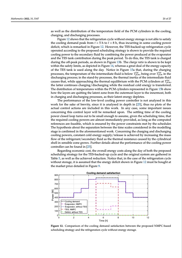
Mathematics 2022, 10, 3167 20 of 27 as well as the distribution of the temperature field of the PCM cylinders in the cooling, charging, and discharging processes. Figure 12 shows that the refrigeration cycle without energy storage is not able to satisfy the cooling demand peak from t = 5 h to t = 8 h, thus incurring in some cooling power deficit, which is remarked in Figure 12. However, the TES-backed-up refrigeration cycle operated according to the proposed scheduling strategy is shown to provide the required cooling power to the secondary fluid by combining the power produced at the evaporator and the TES tank contribution during the peak period. To do this, the TES tank is charged during the off-peak periods, as shown in Figure 13b. The charge ratio is shown to be kept within the safety limits, as depicted in Figure 14, whereas a great deal of the energy capacity of the TES tank is used along the day. Notice in Figure 15a that, during the charging processes, the temperature of the intermediate fluid is below Tlat , being over Tlat in the pcm pcm discharging process; in the stand-by processes, the thermal inertia of the intermediate fluid causesthat,whileapproachingthethermalequilibriumwiththePCMcylindersatTlat , the latter continues charging/discharging while the residual cold energy is transferred. The distribution of temperatures within the PCM cylinders represented in Figure 15b show how the layers are quitting the latent zone from the outermost layer to the innermost, both in charging and discharging processes, as their latent energy depletes. The performance of the low-level cooling power controller is not analysed in this work for the sake of brevity, since it is analysed in depth in [25], thus no plots of the actual control actions are included in this work. In any case, some important issues concerning this control layer will be remarked upon. The settling time of the cooling power closed loop turns out to be small enough to assume, given the scheduling time, that the required cooling powers are almost immediately provided, as long as the computed references are feasible, which is ensured by the power constraints met by the scheduler. The hypothesis about the separation between the time scales considered in the modelling stage is confirmed in the aforementioned work. Concerning the charging and discharging cooling powers, constant cold energy supply/release is achieved by increasing the mass flow of the refrigerant/secondary fluid as the thermal resistance caused by the cylindrical shell in sensible zone grows. Further details about the performance of the cooling power controller can be found in [25]. Regarding economic cost, the overall energy costs along the day of both the proposed scheduling strategy for the TES-backed-up cycle and the original system are gathered in Table 5, as well as the achieved reduction. Notice that, in the case of the refrigeration cycle without storage, it is assumed that the energy deficit shown in Figure 12 must be bought at the market price detailed in Figure 9. pcm 900 800 700 600 500 400 300 200 100 Cooling demand satisfaction Cooling demand Evaporator, NMPC Evaporator, without TES TES, NMPC Deficit, without TES 0 0 2 4 6 8 10 12 Time [h] Figure 12. Comparison of the cooling demand satisfaction between the proposed NMPC-based scheduling strategy and the refrigeration cycle without energy storage. Power [W]PDF Image | Refrigeration Systems with Thermal Energy Storage
PDF Search Title:
Refrigeration Systems with Thermal Energy StorageOriginal File Name Searched:
mathematics-10-03167.pdfDIY PDF Search: Google It | Yahoo | Bing
Turbine and System Plans CAD CAM: Special for this month, any plans are $10,000 for complete Cad/Cam blueprints. License is for one build. Try before you buy a production license. More Info
Waste Heat Power Technology: Organic Rankine Cycle uses waste heat to make electricity, shaft horsepower and cooling. More Info
All Turbine and System Products: Infinity Turbine ORD systems, turbine generator sets, build plans and more to use your waste heat from 30C to 100C. More Info
CO2 Phase Change Demonstrator: CO2 goes supercritical at 30 C. This is a experimental platform which you can use to demonstrate phase change with low heat. Includes integration area for small CO2 turbine, static generator, and more. This can also be used for a GTL Gas to Liquids experimental platform. More Info
Introducing the Infinity Turbine Products Infinity Turbine develops and builds systems for making power from waste heat. It also is working on innovative strategies for storing, making, and deploying energy. More Info
Need Strategy? Use our Consulting and analyst services Infinity Turbine LLC is pleased to announce its consulting and analyst services. We have worked in the renewable energy industry as a researcher, developing sales and markets, along with may inventions and innovations. More Info
Made in USA with Global Energy Millennial Web Engine These pages were made with the Global Energy Web PDF Engine using Filemaker (Claris) software.
Sand Battery Sand and Paraffin for TES Thermo Energy Storage More Info
| CONTACT TEL: 608-238-6001 Email: greg@infinityturbine.com | RSS | AMP |