PDF Publication Title:
Text from PDF Page: 009
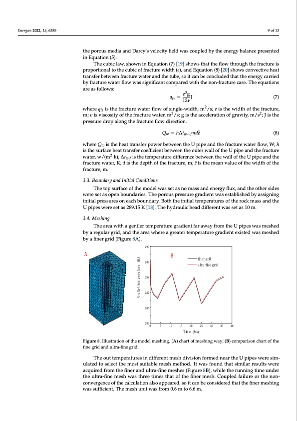
Energies 2022, 15, 6385 The cubic law, shown in Equation (7) [19] shows that the flow through the fracture is proportional to the cubic of fracture width (e), and Equation (8) [20] shows convective heat transfer between fracture water and the tube, so it can be concluded that the energy car- ried by fracture water flow was significant compared with the non-fracture case. The equations are as follows: 9 of 13 qfr = e3g J (7) the porous media and Darcy’s velocity field was coupled by the energy balance presented 12ν where qfr is the fracture water flow of single-width, m2/s; e is the width of the fracture,m; in Equation (5). The cubic law, shown in Equation (7) [19] shows that the flow through the fracture is v is viscosity of the fracture water,m2/s; g is the acceleration of gravity, m/s2; J is the pres- proportional to the cubic of fracture width (e), and Equation (8) [20] shows convective heat sure drop along the fracture flow direction. transfer between fracture water and the tube, so it can be concluded that the energy carried by fracture water flow was significant compared with the non-fracture case. The equations are as follows: Qw =hΔtw−fπde e3g (8) where Qw is the heat transfer power betwqeen=the UJpipe and the fracture water flow, W;(h7) fr where q is2 the fracture water flow of single-width, m2/s; e is the width of the fracture, water, w/f(rm ∙k); Δtw-f is the temperature difference between the wall of the U pipe and the m; v is viscosity of the fracture water, m2/s; g is the acceleration of gravity, m/s2; J is the fracture water, K; d is the depth of the fracture, m; ē is the mean value of the width of the 12ν is the surface heat transfer coefficient between the outer wall of the U pipe and the fracture pressure drop along the fracture flow direction. fracture, m. Qw =h∆tw−fπde (8) The top surface of the model was set as no mass and energy flux, and the other sides 3.3. Boundary and Initial Conditions where Qw is the heat transfer power between the U pipe and the fracture water flow, W; h were set as open boundaries. The porous pressure gradient was established by assigning is the surface heat transfer coefficient between the outer wall of the U pipe and the fracture initial pressur2es on each boundary. Both the initial temperatures of the rock mass and the water, w/(m ·k); ∆tw-f is the temperature difference between the wall of the U pipe and the U pipes were set as 289.15 K [18]. The hydraulic head different was set as 10 m. fracture water, K; d is the depth of the fracture, m; e ̄ is the mean value of the width of the fracture, m. 3.4. Meshing 3.3. Boundary and Initial Conditions The area with a gentler temperature gradient far away from the U pipes was meshed byareTghuelatorpgrsiudr,fancedothfethaeremaowdhelewreaasgseretatsernotemapsesratnudrengerargdyieflnutxe,xaisnteddthweaostmheersshieddes bwyearfeinsetragsriodp(eFnigbuoruen8dAa)r.ies.Theporouspressuregradientwasestablishedbyassigning initial pressures on each boundary. Both the initial temperatures of the rock mass and the The out temperatures in different mesh division formed near the U pipes were sim- U pipes were set as 289.15 K [18]. The hydraulic head different was set as 10 m. ulated to select the most suitable mesh method. It was found that similar results were acquired from the finer and ultra-fine meshes (Figure 8B), while the running time under 3.4. Meshing the ultra-fine mesh was three times that of the finer mesh. Coupled failure or the non- The area with a gentler temperature gradient far away from the U pipes was meshed convergence of the calculation also appeared, so it can be considered that the finer mesh- by a regular grid, and the area where a greater temperature gradient existed was meshed ing was sufficient. The mesh unit was from 0.6 m to 6.6 m. by a finer grid (Figure 8A). 290 289 eruterep 288 meteltu 287 O 286 285 Figure 8. Illustration of the model meshing. (A) chart of meshing way; (B) comparison chart of the Figure 8. Illustration of the model meshing. (A) chart of meshing way; (B) comparison chart of the fifinneeggrirdidanandduultlrtara-f-ifinneeggrirdid.. The out temperatures in different mesh division formed near the U pipes were sim- ulated to select the most suitable mesh method. It was found that similar results were acquired from the finer and ultra-fine meshes (Figure 8B), while the running time under the ultra-fine mesh was three times that of the finer mesh. Coupled failure or the non- convergence of the calculation also appeared, so it can be considered that the finer meshing was sufficient. The mesh unit was from 0.6 m to 6.6 m. 0 5 10 15 20 25 30 35 40 (Ms) (K) B A dir eni gr f-a enif rtlu dirg e miTPDF Image | Research on the Application of Fracture Water
PDF Search Title:
Research on the Application of Fracture WaterOriginal File Name Searched:
energies-15-06385.pdfDIY PDF Search: Google It | Yahoo | Bing
Turbine and System Plans CAD CAM: Special for this month, any plans are $10,000 for complete Cad/Cam blueprints. License is for one build. Try before you buy a production license. More Info
Waste Heat Power Technology: Organic Rankine Cycle uses waste heat to make electricity, shaft horsepower and cooling. More Info
All Turbine and System Products: Infinity Turbine ORD systems, turbine generator sets, build plans and more to use your waste heat from 30C to 100C. More Info
CO2 Phase Change Demonstrator: CO2 goes supercritical at 30 C. This is a experimental platform which you can use to demonstrate phase change with low heat. Includes integration area for small CO2 turbine, static generator, and more. This can also be used for a GTL Gas to Liquids experimental platform. More Info
Introducing the Infinity Turbine Products Infinity Turbine develops and builds systems for making power from waste heat. It also is working on innovative strategies for storing, making, and deploying energy. More Info
Need Strategy? Use our Consulting and analyst services Infinity Turbine LLC is pleased to announce its consulting and analyst services. We have worked in the renewable energy industry as a researcher, developing sales and markets, along with may inventions and innovations. More Info
Made in USA with Global Energy Millennial Web Engine These pages were made with the Global Energy Web PDF Engine using Filemaker (Claris) software.
Sand Battery Sand and Paraffin for TES Thermo Energy Storage More Info
| CONTACT TEL: 608-238-6001 Email: greg@infinityturbine.com | RSS | AMP |