PDF Publication Title:
Text from PDF Page: 019
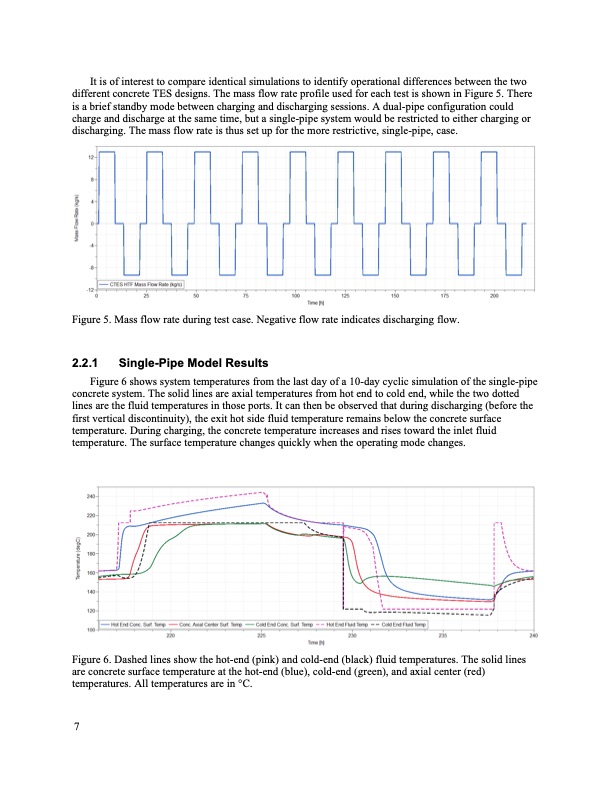
It is of interest to compare identical simulations to identify operational differences between the two different concrete TES designs. The mass flow rate profile used for each test is shown in Figure 5. There is a brief standby mode between charging and discharging sessions. A dual-pipe configuration could charge and discharge at the same time, but a single-pipe system would be restricted to either charging or discharging. The mass flow rate is thus set up for the more restrictive, single-pipe, case. Figure 5. Mass flow rate during test case. Negative flow rate indicates discharging flow. 2.2.1 Single-Pipe Model Results Figure 6 shows system temperatures from the last day of a 10-day cyclic simulation of the single-pipe concrete system. The solid lines are axial temperatures from hot end to cold end, while the two dotted lines are the fluid temperatures in those ports. It can then be observed that during discharging (before the first vertical discontinuity), the exit hot side fluid temperature remains below the concrete surface temperature. During charging, the concrete temperature increases and rises toward the inlet fluid temperature. The surface temperature changes quickly when the operating mode changes. Figure 6. Dashed lines show the hot-end (pink) and cold-end (black) fluid temperatures. The solid lines are concrete surface temperature at the hot-end (blue), cold-end (green), and axial center (red) temperatures. All temperatures are in °C. 7PDF Image | Thermal Energy Storage Model Development
PDF Search Title:
Thermal Energy Storage Model DevelopmentOriginal File Name Searched:
Sort_44972.pdfDIY PDF Search: Google It | Yahoo | Bing
Turbine and System Plans CAD CAM: Special for this month, any plans are $10,000 for complete Cad/Cam blueprints. License is for one build. Try before you buy a production license. More Info
Waste Heat Power Technology: Organic Rankine Cycle uses waste heat to make electricity, shaft horsepower and cooling. More Info
All Turbine and System Products: Infinity Turbine ORD systems, turbine generator sets, build plans and more to use your waste heat from 30C to 100C. More Info
CO2 Phase Change Demonstrator: CO2 goes supercritical at 30 C. This is a experimental platform which you can use to demonstrate phase change with low heat. Includes integration area for small CO2 turbine, static generator, and more. This can also be used for a GTL Gas to Liquids experimental platform. More Info
Introducing the Infinity Turbine Products Infinity Turbine develops and builds systems for making power from waste heat. It also is working on innovative strategies for storing, making, and deploying energy. More Info
Need Strategy? Use our Consulting and analyst services Infinity Turbine LLC is pleased to announce its consulting and analyst services. We have worked in the renewable energy industry as a researcher, developing sales and markets, along with may inventions and innovations. More Info
Made in USA with Global Energy Millennial Web Engine These pages were made with the Global Energy Web PDF Engine using Filemaker (Claris) software.
Sand Battery Sand and Paraffin for TES Thermo Energy Storage More Info
| CONTACT TEL: 608-238-6001 Email: greg@infinityturbine.com | RSS | AMP |