PDF Publication Title:
Text from PDF Page: 034
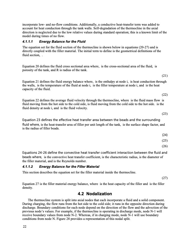
incorporate low- and no-flow conditions. Additionally, a conductive heat-transfer term was added to account for heat conduction through the tank walls. Self-degradation of the thermocline in the axial direction is neglected due to the low relative values during standard operation; this is a known limit of the model during times of no flow. 4.1.1.1 Energy Balance for the Fluid The equation set for the fluid section of the thermocline is shown below in equations (20-27) and is directly coupled with the filler material. The initial term to define is the geometrical definitions of the fluid section, . Equation 20 defines the fluid cross sectional area where, is the cross-sectional area of the fluid, is porosity of the tank, and R is radius of the tank. (21) Equation 21 defines the fluid energy balance where, is the enthalpy at node i, is heat conduction through the walls, is the temperature of the fluid at node i, is the filler temperature at node i, and is the heat capacity of the fluid. (22) Equation 22 defines the average fluid velocity through the thermocline, where is the fluid mass flow is fluid moving from the hot side to the cold side, is fluid moving from the cold side to the hot side. is the fluid density at node i, and is the fluid velocity. (23) Equation 23 defines the effective heat transfer area between the beads and the surrounding fluid where, is the heat-transfer area of filler per unit length of the tank, is the surface shape factor, and is the radius of filler beads. (24) (25) (26) Equations 24-26 define the convective heat transfer coefficient interaction between the fluid and beads where, is the convective heat transfer coefficient, is the characteristic radius, is the diameter of the filler material, and is the Reynolds number. 4.1.1.2 Energy Balance for the Filler Material This section describes the equation set for the filler material inside the thermocline. Equation 27 is the filler material energy balance, where is the heat capacity of the filler and is the filler density. 4.2 Nodalization The thermocline system is split into axial nodes that each incorporate a fluid and a solid component. During charging, the flow runs from the hot side to the cold side; it runs in the opposite direction during discharge. Boundary conditions for each node depend on the direction of the flow and the advection of the previous node’s values. For example, if the thermocline is operating in discharge mode, node N-1 will receive boundary values from node N-2. Whereas, if in charging mode, node N-1 will use boundary conditions from node N. Figure 28 provides a representation of this nodal split. (27) 22PDF Image | Thermal Energy Storage Model Development

PDF Search Title:
Thermal Energy Storage Model DevelopmentOriginal File Name Searched:
Sort_44972.pdfDIY PDF Search: Google It | Yahoo | Bing
Turbine and System Plans CAD CAM: Special for this month, any plans are $10,000 for complete Cad/Cam blueprints. License is for one build. Try before you buy a production license. More Info
Waste Heat Power Technology: Organic Rankine Cycle uses waste heat to make electricity, shaft horsepower and cooling. More Info
All Turbine and System Products: Infinity Turbine ORD systems, turbine generator sets, build plans and more to use your waste heat from 30C to 100C. More Info
CO2 Phase Change Demonstrator: CO2 goes supercritical at 30 C. This is a experimental platform which you can use to demonstrate phase change with low heat. Includes integration area for small CO2 turbine, static generator, and more. This can also be used for a GTL Gas to Liquids experimental platform. More Info
Introducing the Infinity Turbine Products Infinity Turbine develops and builds systems for making power from waste heat. It also is working on innovative strategies for storing, making, and deploying energy. More Info
Need Strategy? Use our Consulting and analyst services Infinity Turbine LLC is pleased to announce its consulting and analyst services. We have worked in the renewable energy industry as a researcher, developing sales and markets, along with may inventions and innovations. More Info
Made in USA with Global Energy Millennial Web Engine These pages were made with the Global Energy Web PDF Engine using Filemaker (Claris) software.
Sand Battery Sand and Paraffin for TES Thermo Energy Storage More Info
| CONTACT TEL: 608-238-6001 Email: greg@infinityturbine.com | RSS | AMP |