PDF Publication Title:
Text from PDF Page: 022
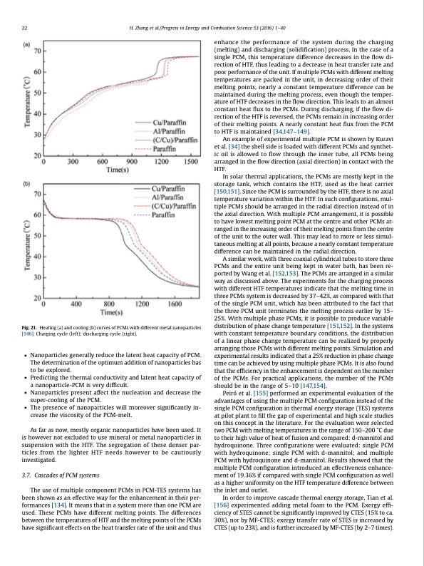
22 H. Zhang et al./Progress in Energy and Combustion Science 53 (2016) 1–40 Fig.21. Heating(a)andcooling(b)curvesofPCMswithdifferentmetalnanoparticles [146]. Charging cycle (left); discharging cycle (right). • Nanoparticles generally reduce the latent heat capacity of PCM. The determination of the optimum addition of nanoparticles has to be explored. • Predicting the thermal conductivity and latent heat capacity of a nanoparticle-PCM is very difficult. • Nanoparticles present affect the nucleation and decrease the super-cooling of the PCM. • The presence of nanoparticles will moreover significantly in- crease the viscosity of the PCM-melt. As far as now, mostly organic nanoparticles have been used. It is however not excluded to use mineral or metal nanoparticles in suspension with the HTF. The segregation of these denser par- ticles from the lighter HTF needs however to be cautiously investigated. 3.7. CascadesofPCMsystems The use of multiple component PCMs in PCM-TES systems has been shown as an effective way for the enhancement in their per- formances [134]. It means that in a system more than one PCM are used. These PCMs have different melting points. The differences between the temperatures of HTF and the melting points of the PCMs have significant effects on the heat transfer rate of the unit and thus enhance the performance of the system during the charging (melting) and discharging (solidification) process. In the case of a single PCM, this temperature difference decreases in the flow di- rection of HTF, thus leading to a decrease in heat transfer rate and poor performance of the unit. If multiple PCMs with different melting temperatures are packed in the unit, in decreasing order of their melting points, nearly a constant temperature difference can be maintained during the melting process, even though the temper- ature of HTF decreases in the flow direction. This leads to an almost constant heat flux to the PCMs. During discharging, if the flow di- rection of the HTF is reversed, the PCMs remain in increasing order of their melting points. A nearly constant heat flux from the PCM to HTF is maintained [34,147–149]. An example of experimental multiple PCM is shown by Kuravi et al. [34] the shell side is loaded with different PCMs and synthet- ic oil is allowed to flow through the inner tube, all PCMs being arranged in the flow direction (axial direction) in contact with the HTF. In solar thermal applications, the PCMs are mostly kept in the storage tank, which contains the HTF, used as the heat carrier [150,151]. Since the PCM is surrounded by the HTF, there is no axial temperature variation within the HTF. In such configurations, mul- tiple PCMs should be arranged in the radial direction instead of in the axial direction. With multiple PCM arrangement, it is possible to have lowest melting point PCM at the centre and other PCMs ar- ranged in the increasing order of their melting points from the centre of the unit to the outer wall. This may lead to more or less simul- taneous melting at all points, because a nearly constant temperature difference can be maintained in the radial direction. A similar work, with three coaxial cylindrical tubes to store three PCMs and the entire unit being kept in water bath, has been re- ported by Wang et al. [152,153]. The PCMs are arranged in a similar way as discussed above. The experiments for the charging process with different HTF temperatures indicate that the melting time in three PCMs system is decreased by 37–42%, as compared with that of the single PCM unit, which has been attributed to the fact that the three PCM unit terminates the melting process earlier by 15– 25%. With multiple phase PCMs, it is possible to produce variable distribution of phase change temperature [151,152]. In the systems with constant temperature boundary conditions, the distribution of a linear phase change temperature can be realized by properly arranging those PCMs with different melting points. Simulation and experimental results indicated that a 25% reduction in phase change time can be achieved by using multiple phase PCMs. It is also found that the efficiency in the enhancement is dependent on the number of the PCMs. For practical applications, the number of the PCMs should be in the range of 5–10 [147,154]. Peiró et al. [155] performed an experimental evaluation of the advantages of using the multiple PCM configuration instead of the single PCM configuration in thermal energy storage (TES) systems at pilot plant to fill the gap of experimental and high scale studies on this concept in the literature. For the evaluation were selected two PCM with melting temperatures in the range of 150–200 °C due to their high value of heat of fusion and compared: d-mannitol and hydroquinone. Three configurations were evaluated: single PCM with hydroquinone; single PCM with d-mannitol; and multiple PCM with hydroquinone and d-mannitol. Results showed that the multiple PCM configuration introduced an effectiveness enhance- ment of 19.36% if compared with single PCM configuration as well as a higher uniformity on the HTF temperature difference between the inlet and outlet. In order to improve cascade thermal energy storage, Tian et al. [156] experimented adding metal foam to the PCM. Exergy effi- ciency of STES cannot be significantly improved by CTES (15% to ca. 30%), nor by MF-CTES; exergy transfer rate of STES is increased by CTES (up to 23%), and is further increased by MF-CTES (by 2–7 times).PDF Image | Thermal energy storage: Recent developments
PDF Search Title:
Thermal energy storage: Recent developmentsOriginal File Name Searched:
3-Thermal-Energy-storage-recent-developments-and-practical-aspects.pdfDIY PDF Search: Google It | Yahoo | Bing
Turbine and System Plans CAD CAM: Special for this month, any plans are $10,000 for complete Cad/Cam blueprints. License is for one build. Try before you buy a production license. More Info
Waste Heat Power Technology: Organic Rankine Cycle uses waste heat to make electricity, shaft horsepower and cooling. More Info
All Turbine and System Products: Infinity Turbine ORD systems, turbine generator sets, build plans and more to use your waste heat from 30C to 100C. More Info
CO2 Phase Change Demonstrator: CO2 goes supercritical at 30 C. This is a experimental platform which you can use to demonstrate phase change with low heat. Includes integration area for small CO2 turbine, static generator, and more. This can also be used for a GTL Gas to Liquids experimental platform. More Info
Introducing the Infinity Turbine Products Infinity Turbine develops and builds systems for making power from waste heat. It also is working on innovative strategies for storing, making, and deploying energy. More Info
Need Strategy? Use our Consulting and analyst services Infinity Turbine LLC is pleased to announce its consulting and analyst services. We have worked in the renewable energy industry as a researcher, developing sales and markets, along with may inventions and innovations. More Info
Made in USA with Global Energy Millennial Web Engine These pages were made with the Global Energy Web PDF Engine using Filemaker (Claris) software.
Sand Battery Sand and Paraffin for TES Thermo Energy Storage More Info
| CONTACT TEL: 608-238-6001 Email: greg@infinityturbine.com | RSS | AMP |