PDF Publication Title:
Text from PDF Page: 009
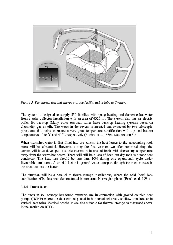
Figure 5. The cavern thermal energy storage facility at Lyckebo in Sweden. The system is designed to supply 550 families with space heating and domestic hot water from a solar collector installation with an area of 4320 m2. The system also has an electric boiler for back-up (Many other seasonal stores have back-up heating systems based on electricity, gas or oil). The water in the cavern is inserted and extracted by two telescopic pipes, and this helps to ensure a very good temperature stratification with top and bottom temperatures of 90 oC and 40 oC respectively (Pilebro et al, 1986). (See section 3.2). When warm/hot water is first filled into the cavern, the heat losses to the surrounding rock mass will be substantial. However, during the first year or two after commissioning, the cavern will have developed a stable thermal halo around itself with decreasing temperature away from the warm/hot centre. There will still be a loss of heat, but dry rock is a poor heat conductor. The heat loss should be less than 10% during one operational cycle under favourable conditions. A crucial factor is ground water transport through the rock masses in the area, the less the better. The situation will be a parallel to freeze storage installations, where the cold (heat) loss stabilisation effect has been demonstrated in numerous Norwegian plants (Broch et al, 1994). 3.1.4 Ducts in soil The ducts in soil concept has found extensive use in connection with ground coupled heat pumps (GCHP) where the duct can be placed in horizontal relatively shallow trenches, or in vertical boreholes. Vertical boreholes are also suitable for thermal storage as discussed above in the section on BTES. 9PDF Image | Thermal Energy Storage A State-of-the-Art
PDF Search Title:
Thermal Energy Storage A State-of-the-ArtOriginal File Name Searched:
thermal-energy-storage.pdfDIY PDF Search: Google It | Yahoo | Bing
Turbine and System Plans CAD CAM: Special for this month, any plans are $10,000 for complete Cad/Cam blueprints. License is for one build. Try before you buy a production license. More Info
Waste Heat Power Technology: Organic Rankine Cycle uses waste heat to make electricity, shaft horsepower and cooling. More Info
All Turbine and System Products: Infinity Turbine ORD systems, turbine generator sets, build plans and more to use your waste heat from 30C to 100C. More Info
CO2 Phase Change Demonstrator: CO2 goes supercritical at 30 C. This is a experimental platform which you can use to demonstrate phase change with low heat. Includes integration area for small CO2 turbine, static generator, and more. This can also be used for a GTL Gas to Liquids experimental platform. More Info
Introducing the Infinity Turbine Products Infinity Turbine develops and builds systems for making power from waste heat. It also is working on innovative strategies for storing, making, and deploying energy. More Info
Need Strategy? Use our Consulting and analyst services Infinity Turbine LLC is pleased to announce its consulting and analyst services. We have worked in the renewable energy industry as a researcher, developing sales and markets, along with may inventions and innovations. More Info
Made in USA with Global Energy Millennial Web Engine These pages were made with the Global Energy Web PDF Engine using Filemaker (Claris) software.
Sand Battery Sand and Paraffin for TES Thermo Energy Storage More Info
| CONTACT TEL: 608-238-6001 Email: greg@infinityturbine.com | RSS | AMP |