PDF Publication Title:
Text from PDF Page: 005
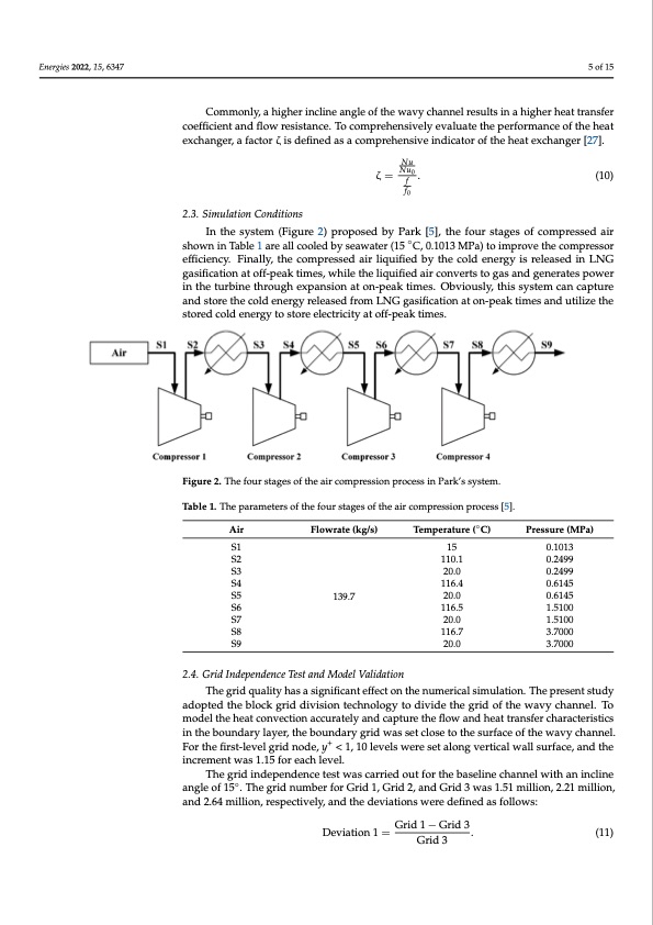
Energies 2022, 15, 6347 and outlet working fluids, respectively. 𝑢, 𝑢 are the inlet and outlet velocity, respe tively. Lp is the flow channel length. Commonly, a higher incline angle of the wavy channel results in a higher heat transf 5 of 15 coefficient and flow resistance. To comprehensively evaluate the performance of the he exchanger, a factor ζ is defined as a comprehensive indicator of the heat exchanger [27]. Commonly, a higher incline angle of the wavy channel results in a higher heat transfer 𝑁𝑢 coefficient and flow resistance. To comprehensively evaluate the performance of the heat 𝑁𝑢 ζ= . (10) exchanger, a factor ζ is defined as a comprehensiv𝑓e indicator of the heat exchanger [27]. Nu 𝑓 ζ = Nu0 . (10) f 2.3. Simulation Conditions f0 In the system (Figure 2) proposed by Park [5], the four stages of compressed a 2.3. Simulation Conditions shown in Table 1 are all cooled by seawater (15 °C, 0.1013 MPa) to improve the compress In the system (Figure 2) proposed by Park [5], the four stages of compressed air efficiency. Finally, the compressed air liquified by the cold energy is released in LNG ga shown in Table 1 are all cooled by seawater (15 ◦C, 0.1013 MPa) to improve the compressor ificaeftfiiocnienactyo. fFf-inpaelalyk, thime ecosm, wprheislseedthaeirlilqiquuiiffiied abyirtchoencvoeldrtesnteorgyasisarneldeagsedneinraLteNsGpower i gasification at off-peak times, while the liquified air converts to gas and generates power the turbine through expansion at on-peak times. Obviously, this system can capture an in the turbine through expansion at on-peak times. Obviously, this system can capture store the cold energy released from LNG gasification at on-peak times and utilize th and store the cold energy released from LNG gasification at on-peak times and utilize the stored cold energy to store electricity at off-peak times. stored cold energy to store electricity at off-peak times. Figure 2. The four stages of the air compression process in Park’s system. Figure 2. The four stages of the air compression process in Park’s system. Table 1. The parameters of the four stages of the air compression process [5]. Table 1. The parameters of the four stages of the air compression process [5]. Air Air Flowrate (kg/s) Temperature (◦C) Flowrate (kg/s) Temperature (°C) S1 15 15 S4 116.4 Pressure (MPa) Pressure (MPa) S1 S2 S3 S4 S5 S6 S7 S2 110.1 S3 20.0 0.1013 0.2499 0.2499 0.6145 0.6145 1.5100 1.5100 3.7000 3.7000 0.1013 0.2499 0.2499 0.6145 0.6145 1.5100 1.5100 3.7000 S5 139.7 20.0 S6 11616.4.5 S7 20.0 139.7 20.0 S8 116.7 20.0 2.4S.8Grid Independence Test and Model Validation 116.7 S9 20.0 110.1 20.0 116.5 S9The grid quality has a significant effect on the num20e.r0ical simulation. The presen3t.7st0u0d0y adopted the block grid division technology to divide the grid of the wavy channel. To model the heat convection accurately and capture the flow and heat transfer characteristics 2.4. Grid Independence Test and Model Validation in the boundary layer, the boundary grid was set close to the surface of the wavy channel. The grid quality has a significant effect on the numerical simulation. The prese For the first-level grid node, y+ < 1, 10 levels were set along vertical wall surface, and the studinycraedmoepntewdasth1e.15blforckeagchridlevdeilv. ision technology to divide the grid of the wavy channe The grid independence test was carried out for the baseline channel with an incline To model the heat convection accurately and capture the flow and heat transfer characte angle of 15◦. The grid number for Grid 1, Grid 2, and Grid 3 was 1.51 million, 2.21 million, istics in the boundary layer, the boundary grid was set close to the surface of the wav and 2.64 million, respectively, and the deviations were defined as follows: channel. For the first-level grid node, y+ < 1, 10 levels were set along vertical wall surfac and the increment was 1.15 for each level.Grid 1 − Grid 3 Deviation 1 = Grid 3 . (11) The grid independence test was carried out for the baseline channel with an inclin angle of 15°. The grid number for Grid 1, Grid 2, and Grid 3 was 1.51 million, 2.21 millio and 2.64 million, respectively, and the deviations were defined as follows: c e a i o s n d n r e nPDF Image | Thermal–Hydraulic Performance of a Printed Circuit Heat Exchanger
PDF Search Title:
Thermal–Hydraulic Performance of a Printed Circuit Heat ExchangerOriginal File Name Searched:
energies-15-06347.pdfDIY PDF Search: Google It | Yahoo | Bing
Turbine and System Plans CAD CAM: Special for this month, any plans are $10,000 for complete Cad/Cam blueprints. License is for one build. Try before you buy a production license. More Info
Waste Heat Power Technology: Organic Rankine Cycle uses waste heat to make electricity, shaft horsepower and cooling. More Info
All Turbine and System Products: Infinity Turbine ORD systems, turbine generator sets, build plans and more to use your waste heat from 30C to 100C. More Info
CO2 Phase Change Demonstrator: CO2 goes supercritical at 30 C. This is a experimental platform which you can use to demonstrate phase change with low heat. Includes integration area for small CO2 turbine, static generator, and more. This can also be used for a GTL Gas to Liquids experimental platform. More Info
Introducing the Infinity Turbine Products Infinity Turbine develops and builds systems for making power from waste heat. It also is working on innovative strategies for storing, making, and deploying energy. More Info
Need Strategy? Use our Consulting and analyst services Infinity Turbine LLC is pleased to announce its consulting and analyst services. We have worked in the renewable energy industry as a researcher, developing sales and markets, along with may inventions and innovations. More Info
Made in USA with Global Energy Millennial Web Engine These pages were made with the Global Energy Web PDF Engine using Filemaker (Claris) software.
Sand Battery Sand and Paraffin for TES Thermo Energy Storage More Info
| CONTACT TEL: 608-238-6001 Email: greg@infinityturbine.com | RSS | AMP |