PDF Publication Title:
Text from PDF Page: 011
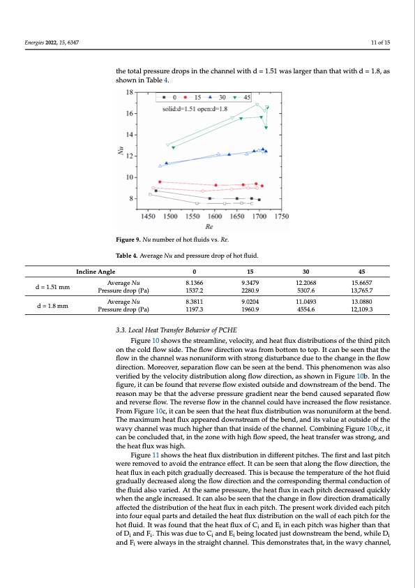
Energies 2022, 15, 6347 when the incline angle was 45°, except for the first pitch, Nu in the channel with d = 1. 11 of 15 d = 1.51 mm 8.1366 9.3479 12.2068 d = 1.51 mm Pressure drop (Pa) 1537.2 2280.9 5307.6 5307.6 d = 1.8 mm d = 1.8 mm Pressure drop (Pa) 8.3811 9.0204 11.0493 Incline Angle 45 15.6657 13,765.7 in the channel with d = 1.51 mm was larger than that of the channel with d = 1.8 mm. Whe the incline angle was 30°, the Nu of the two channels was almost the same. However mm was larger than that with d = 1.51 mm. This result indicates that, when the inclin angle was small, the small-diameter channel showed better heat transfer performance. I addition, the total pressure drops in the channel with d = 1.51 was larger than that with the total pressure drops in the channel with d = 1.51 was larger than that with d = 1.8, as = 1.8, as shown in Table 4. shown in Table 4. Figure 9. Nu number of hot fluids vs. Re. Figure 9. Nu number of hot fluids vs. Re. Table 4. Average Nu and pressure drop of hot fluid. Table 4. Average Nu and pressure drop of hot fluid. Incline Angle 0 0 15 15 30 30 45 15.6657 13,765.7 13.0880 12,109.3 Average Nu Average Nu 8.1366 9.3479 12.2068 Pressure drop (Pa) 1537.2 2280.9 Average Nu Average Nu 8.3811 9.0204 11.0493 13.0880 12,109.3 Pressure drop (Pa) 1197.3 1960.9 4554.6 1197.3 1960.9 4554.6 3.3. Local Heat Transfer Behavior of PCHE 3.3. Local Heat Transfer Behavior of PCHE Figure 10 shows the streamline, velocity, and heat flux distributions of the third pitch Figure 10 shows the streamline, velocity, and heat flux distributions of the third pitc on the cold flow side. The flow direction was from bottom to top. It can be seen that the oflnowthinetchoeldchfalonnwelswidaes.nTohneunfliofowrmdwirietchtsiotrnonwgadsisftruormbanbcoetdtoumetotothtoepch.aItngceaninbtehesfleeonwthatth direction. Moreover, separation flow can be seen at the bend. This phenomenon was also flow in the channel was nonuniform with strong disturbance due to the change in the flo verified by the velocity distribution along flow direction, as shown in Figure 10b. In the direction. Moreover, separation flow can be seen at the bend. This phenomenon was als figure, it can be found that reverse flow existed outside and downstream of the bend. The verified by the velocity distribution along flow direction, as shown in Figure 10b. In th reason may be that the adverse pressure gradient near the bend caused separated flow figure, it can be found that reverse flow existed outside and downstream of the bend. Th and reverse flow. The reverse flow in the channel could have increased the flow resistance. reason may be that the adverse pressure gradient near the bend caused separated flo From Figure 10c, it can be seen that the heat flux distribution was nonuniform at the bend. and reverse flow. The reverse flow in the channel could have increased the flow resistance The maximum heat flux appeared downstream of the bend, and its value at outside of the From Figure 10c, it can be seen that the heat flux distribution was nonuniform at the bend wavy channel was much higher than that inside of the channel. Combining Figure 10b,c, it Tcahnebme acoxnimcludmedhtehaatt,fliunxthaepzpoenaerwedithdohwignhsfltorewamspeoefdt,htehebheneadt,taranndsfietrswvalsusetraotnog,uatnside of th the heat flux was high. wavy channel was much higher than that inside of the channel. Combining Figure 10b,c Figure 11 shows the heat flux distribution in different pitches. The first and last pitch it can be concluded that, in the zone with high flow speed, the heat transfer was strong were removed to avoid the entrance effect. It can be seen that along the flow direction, the and the heat flux was high. heat flux in each pitch gradually decreased. This is because the temperature of the hot fluid gradually decreased along the flow direction and the corresponding thermal conduction of the fluid also varied. At the same pressure, the heat flux in each pitch decreased quickly when the angle increased. It can also be seen that the change in flow direction dramatically affected the distribution of the heat flux in each pitch. The present work divided each pitch into four equal parts and detailed the heat flux distribution on the wall of each pitch for the hot fluid. It was found that the heat flux of Ci and Ei in each pitch was higher than that of Di and Fi. This was due to Ci and Ei being located just downstream the bend, while Di and Fi were always in the straight channel. This demonstrates that, in the wavy channel, n , 8 e n d h e w o e e w . . e , ,PDF Image | Thermal–Hydraulic Performance of a Printed Circuit Heat Exchanger
PDF Search Title:
Thermal–Hydraulic Performance of a Printed Circuit Heat ExchangerOriginal File Name Searched:
energies-15-06347.pdfDIY PDF Search: Google It | Yahoo | Bing
Turbine and System Plans CAD CAM: Special for this month, any plans are $10,000 for complete Cad/Cam blueprints. License is for one build. Try before you buy a production license. More Info
Waste Heat Power Technology: Organic Rankine Cycle uses waste heat to make electricity, shaft horsepower and cooling. More Info
All Turbine and System Products: Infinity Turbine ORD systems, turbine generator sets, build plans and more to use your waste heat from 30C to 100C. More Info
CO2 Phase Change Demonstrator: CO2 goes supercritical at 30 C. This is a experimental platform which you can use to demonstrate phase change with low heat. Includes integration area for small CO2 turbine, static generator, and more. This can also be used for a GTL Gas to Liquids experimental platform. More Info
Introducing the Infinity Turbine Products Infinity Turbine develops and builds systems for making power from waste heat. It also is working on innovative strategies for storing, making, and deploying energy. More Info
Need Strategy? Use our Consulting and analyst services Infinity Turbine LLC is pleased to announce its consulting and analyst services. We have worked in the renewable energy industry as a researcher, developing sales and markets, along with may inventions and innovations. More Info
Made in USA with Global Energy Millennial Web Engine These pages were made with the Global Energy Web PDF Engine using Filemaker (Claris) software.
Sand Battery Sand and Paraffin for TES Thermo Energy Storage More Info
| CONTACT TEL: 608-238-6001 Email: greg@infinityturbine.com | RSS | AMP |