PDF Publication Title:
Text from PDF Page: 012
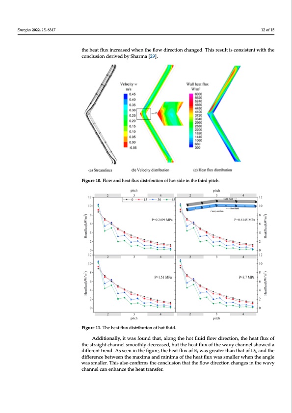
Energies 2022, 15, 6347 12 of 15 Energies 2022, 15, x FOR PEER REVIEW the heat flux increased when the flow direction changed. This result is consistent with the conclusion derived by Sharma [29]. Figure 10. Flow and heat flux distribution of hot side in the third pitch. Figure 11 shows the heat flux distribution in different pitches. The first and last pitc were removed to avoid the entrance effect. It can be seen that along the flow direction, th heat flux in each pitch gradually decreased. This is because the temperature of the ho fluid gradually decreased along the flow direction and the corresponding thermal con duction of the fluid also varied. At the same pressure, the heat flux in each pitch decrease quickly when the angle increased. It can also be seen that the change in flow directio dramatically affected the distribution of the heat flux in each pitch. The present work di vided each pitch into four equal parts and detailed the heat flux distribution on the wa of each pitch for the hot fluid. It was found that the heat flux of Ci and Ei in each pitch wa higher than that of Di and Fi. This was due to Ci and Ei being located just downstream th bend, while Di and Fi were always in the straight channel. This demonstrates that, in th wavy channel, the heat flux increased when the flow direction changed. This result is con sistent with the conclusion derived by Sharma [29]. Figure 10. Flow and heat flux distribution of hot side in the third pitch. Figure 10. Flow and heat flux distribution of hot side in the third pitch. Figure 11 shows the heat flux distribution in different pitches. The first and l were removed to avoid the entrance effect. It can be seen that along the flow dire heat flux in each pitch gradually decreased. This is because the temperature o fluid gradually decreased along the flow direction and the corresponding ther duction of the fluid also varied. At the same pressure, the heat flux in each pitch d quickly when the angle increased. It can also be seen that the change in flow dramatically affected the distribution of the heat flux in each pitch. The present vided each pitch into four equal parts and detailed the heat flux distribution on of each pitch for the hot fluid. It was found that the heat flux of Ci and Ei in each higher than that of Di and Fi. This was due to Ci and Ei being located just downst bend, while Di and Fi were always in the straight channel. This demonstrates th wavy channel, the heat flux increased when the flow direction changed. This resu sistent with the conclusion derived by Sharma [29]. Fiiguurree11.1T. Thehehehaetafltufxludxisdtrisbturtiibountioofnhotfflhuoitd.fluid. Additionally, it was found that, along the hot fluid flow direction, the heat flux of the straight channel smoothly decreased, but the heat flux of the wavy channel showed a different trend. As seen in the figure, the heat flux of Ei was greater than that of Di, and the difference between the maxima and minima of the heat flux was smaller when the angle was smaller. This also confirms the conclusion that the flow direction changes in the wavy channel can enhance the heat transfer. h e d n l e e c f m e d w p r aPDF Image | Thermal–Hydraulic Performance of a Printed Circuit Heat Exchanger
PDF Search Title:
Thermal–Hydraulic Performance of a Printed Circuit Heat ExchangerOriginal File Name Searched:
energies-15-06347.pdfDIY PDF Search: Google It | Yahoo | Bing
Turbine and System Plans CAD CAM: Special for this month, any plans are $10,000 for complete Cad/Cam blueprints. License is for one build. Try before you buy a production license. More Info
Waste Heat Power Technology: Organic Rankine Cycle uses waste heat to make electricity, shaft horsepower and cooling. More Info
All Turbine and System Products: Infinity Turbine ORD systems, turbine generator sets, build plans and more to use your waste heat from 30C to 100C. More Info
CO2 Phase Change Demonstrator: CO2 goes supercritical at 30 C. This is a experimental platform which you can use to demonstrate phase change with low heat. Includes integration area for small CO2 turbine, static generator, and more. This can also be used for a GTL Gas to Liquids experimental platform. More Info
Introducing the Infinity Turbine Products Infinity Turbine develops and builds systems for making power from waste heat. It also is working on innovative strategies for storing, making, and deploying energy. More Info
Need Strategy? Use our Consulting and analyst services Infinity Turbine LLC is pleased to announce its consulting and analyst services. We have worked in the renewable energy industry as a researcher, developing sales and markets, along with may inventions and innovations. More Info
Made in USA with Global Energy Millennial Web Engine These pages were made with the Global Energy Web PDF Engine using Filemaker (Claris) software.
Sand Battery Sand and Paraffin for TES Thermo Energy Storage More Info
| CONTACT TEL: 608-238-6001 Email: greg@infinityturbine.com | RSS | AMP |