PDF Publication Title:
Text from PDF Page: 008
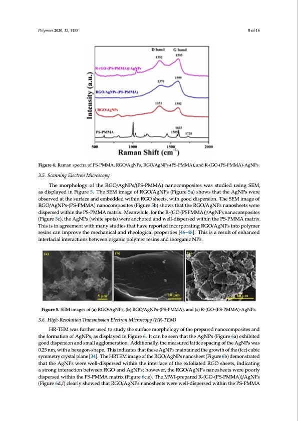
Polymers 2020, 12, x FOR PEER REVIEW 8 of 16 Polymers 2020, 12, 1155 Polymers 2020, 12, x FOR PEER REVIEW 8 of 16 8 of 16 Figure 4. Raman spectra of PS-PMMA, RGO/AgNPs, RGO/AgNPs-(PS-PMMA), and R-(GO-(PS- PMMA)-AgNPs. Figure 4. Raman spectra of PS-PMMA, RGO/AgNPs, RGO/AgNPs-(PS-PMMA), and R-(GO-(PS- Figure 4. Raman spectra of PS-PMMA, RGO/AgNPs, RGO/AgNPs-(PS-PMMA), and R-(GO-(PS-PMMA)-AgNPs. PMMA)-AgNPs. 3.5. Scanning Electron Microscopy 3.5. Scanning Electron Microscopy T3.h5e. SmcaonrnpinhgoElolegctyroonfMthiceroRscGopOy/AgNPs/(PS-PMMA) nanocomposites was studied using SEM, as The morphology of the RGO/AgNPs/(PS-PMMA) nanocomposites was studied using SEM, displayed in Figure 5. The SEM image of RGO/AgNPs (Figure 5a) shows that the AgNPs were as displTahyedmionrpFhiogluorgey5o.fTtheRSGEMO/AimgNagPes/o(PfSR-PGMOM/AAg)NnPasno(Fcoigmuproes5itae)sswhaoswsstutdhiaetdthuesiAngNSEPMs,waesre observed at the surface and embedded within RGO sheets, with good dispersion. The SEM image of displayed in Figure 5. The SEM image of RGO/AgNPs (Figure 5a) shows that the AgNPs were observed at the surface and embedded within RGO sheets, with good dispersion. The SEM image of RGO/AgNPs-(PS-PMMA) nanocomposites (Figure 5b) shows that the RGO/AgNPs nanosheets were observed at the surface and embedded within RGO sheets, with good dispersion. The SEM image of RGO/AgNPs-(PS-PMMA) nanocomposites (Figure 5b) shows that the RGO/AgNPs nanosheets were dispeRrsGeOd/AgwNitPhsi-n(PSt-PhMe MPAS)-PnaMnoMcoAmpmosaitersix(.FigMurea5nbw) shiolew,s tfhoart thtehReGOR/-A(GgONPs(nPaSnPoMshMeeAts)w)/eAregNPs dispersed within the PS-PMMA matrix. Meanwhile, for the R-(GO (PSPMMA))/AgNPs nanocomposites dispersed within the PS-PMMA matrix. Meanwhile, for the R-(GO (PSPMMA))/AgNPs nanocomposites (Figure 5c), the AgNPs (white spots) were anchored and well-dispersed within the (Figure 5c), the AgNPs (white spots) were anchored and well-dispersed within the PS-PMMA matrix. nanocomposites (Figure 5c), the AgNPs (white spots) were anchored and well-dispersed within the PS-PMMA matrix. This is in agreement with many studies that have reported incorporating This is in agreement with many studies that have reported incorporating RGO/AgNPs into polymer PS-PMMA matrix. This is in agreement with many studies that have reported incorporating RGreOs/inAsgcNanPsiminptoropvoelythmeemr reecshiannsicanl aimndprhoevoeltohgeicmalepchroapneirctaileasn[4d6r–h4e8o].loTghiicsailsparorpeseurtltieosf[e4n6h–4a8n]c.eTdhis RGO/AgNPs into polymer resins can improve the mechanical and rheological properties [46–48]. This is ainrtesrfualctiaolf ienntehranctcieodnsinbtetrwfaeceinaloirngtaenriaccptiolnysmbeertrweseienns oanrgdainiocrgpaonlyicmNePr sr.esins and inorganic NPs. is a result of enhanced interfacial interactions between organic polymer resins and inorganic NPs. Figure 5. SEM images of (a) RGO/AgNPs, (b) RGO/AgNPs-(PS-PMMA), and (c) R-(GO-(PS-PMMA)- Figure 5. SEM images of (a) RGO/AgNPs, (b) RGO/AgNPs-(PS-PMMA), and (c) R-(GO-(PS-PMMA)-AgNPs. Figure 5. SEM images of (a) RGO/AgNPs, (b) RGO/AgNPs-(PS-PMMA), and (c) R-(GO-(PS-PMMA)- AgNPs. AgNPs. 3.6. High-Resolution Transmission Electron Microscopy (HR-TEM) 3.6. High-Resolution Transmission Electron Microscopy (HR-TEM) HR-TEM was further used to study the surface morphology of the prepared nanocomposites and 3.6. High-Resolution Transmission Electron Microscopy (HR-TEM) HR-TEM was further used to study the surface morphology of the prepared nanocomposites the formation of AgNPs, as displayed in Figure 6. It can be seen that the AgNPs (Figure 6a) exhibited HanRd-TthEeMforwmaastifounrtohfeArguNsPeds, taos dstiuspdlyaytehdeinsuFrifgaucreem6.oIrtpchaonlobegyseoenf theatptrhepAargeNdPsna(Fniogcuorem6pao)sites good dispersion and small agglomeration. Additionally, the measured lattice spacing of the AgNPs was andtehxehifboitremdagtoiondodfispAegrsNioPns,anadsdsmisapllaaygegdlominerFaitgiounr.eA6d.dItiticoannalblye,tsheenmethasautrtehdelaAttgicNePspsa(cFiniguorfe6a) 0.25 nm, with a hexagon-shape. This indicates that these AgNPs maintained the growth of the (fcc) cubic the AgNPs was 0.25 nm, with a hexagon-shape. This indicates that these AgNPs maintained the exhibited good dispersion and small agglomeration. Additionally, the measured lattice spacing of symmetry crystal plane [34]. The HRTEM image of the RGO/AgNPs nanosheet (Figure 6b) demonstrated growth of the (fcc) cubic symmetry crystal plane [34]. The HRTEM image of the RGO/AgNPs the AgNPs was 0.25 nm, with a hexagon-shape. This indicates that these AgNPs maintained the that the AgNPs were well-dispersed within the interface of the exfoliated RGO sheets, indicating nanosheet (Figure 6b) demonstrated that the AgNPs were well-dispersed within the interface of the growth of the (fcc) cubic symmetry crystal plane [34]. The HRTEM image of the RGO/AgNPs a strong interaction between RGO and AgNPs; however, the RGO/AgNPs nanosheets were poorly exfoliated RGO sheets, indicating a strong interaction between RGO and AgNPs; however, the nadniosspheerseetd(Fwigituhrine 6thbe)PdSe-mPMonMstAramteadtrtihxa(tFitghuereA6gcN,eP).sTwherMeWweI-lpl-rdeipsaprerdseRd-(GwOit-h(PinS-tPhMe iMntAe)r)f/aAcgeNoPfsthe RGO/AgNPs nanosheets were poorly dispersed within the PS-PMMA matrix (Figure 6c,e). The MWI- ex(fFoilgiautreed6dR,Gf)Oclesahrleyestsh,owineddictahtaintgRGaOs/AtrogNngPsintaenroaschtieoentsbweetrweewenell-RdGisOperasnedwAigthNinPsth;ehPoSw-PeMveMr,Athe RGO/AgNPs nanosheets were poorly dispersed within the PS-PMMA matrix (Figure 6c,e). The MWI-PDF Image | Microwave Irradiation Synthesis Silver Nanoparticle
PDF Search Title:
Microwave Irradiation Synthesis Silver NanoparticleOriginal File Name Searched:
polymers-12-01155-v2.pdfDIY PDF Search: Google It | Yahoo | Bing
Turbine and System Plans CAD CAM: Special for this month, any plans are $10,000 for complete Cad/Cam blueprints. License is for one build. Try before you buy a production license. More Info
Waste Heat Power Technology: Organic Rankine Cycle uses waste heat to make electricity, shaft horsepower and cooling. More Info
All Turbine and System Products: Infinity Turbine ORD systems, turbine generator sets, build plans and more to use your waste heat from 30C to 100C. More Info
CO2 Phase Change Demonstrator: CO2 goes supercritical at 30 C. This is a experimental platform which you can use to demonstrate phase change with low heat. Includes integration area for small CO2 turbine, static generator, and more. This can also be used for a GTL Gas to Liquids experimental platform. More Info
Introducing the Infinity Turbine Products Infinity Turbine develops and builds systems for making power from waste heat. It also is working on innovative strategies for storing, making, and deploying energy. More Info
Need Strategy? Use our Consulting and analyst services Infinity Turbine LLC is pleased to announce its consulting and analyst services. We have worked in the renewable energy industry as a researcher, developing sales and markets, along with may inventions and innovations. More Info
Made in USA with Global Energy Millennial Web Engine These pages were made with the Global Energy Web PDF Engine using Filemaker (Claris) software.
Infinity Turbine Developing Spinning Disc Reactor SDR or Spinning Disc Reactors reduce processing time for liquid production of Silver Nanoparticles.
| CONTACT TEL: 608-238-6001 Email: greg@infinityturbine.com | RSS | AMP |