PDF Publication Title:
Text from PDF Page: 010
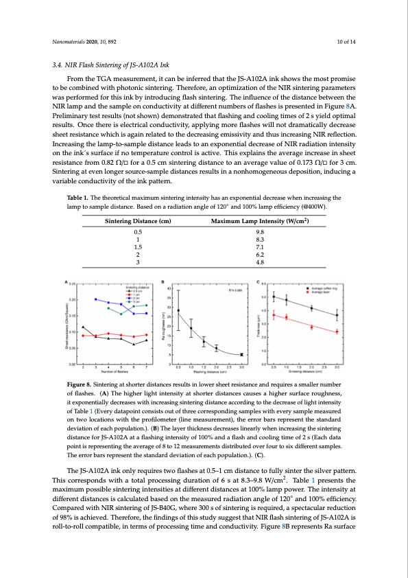
Nanomaterials 2020, 10, 892 10 of 14 3.4. NIR Flash Sintering of JS-A102A Ink From the TGA measurement, it can be inferred that the JS-A102A ink shows the most promise Nanomaterials 2020, 10, x FOR PEER REVIEW 11 of 14 to be combined with photonic sintering. Therefore, an optimization of the NIR sintering parameters was performed for this ink by introducing flash sintering. The influence of the distance between the mechanisms (capillary flow and Marangoni flow). The optimization towards this balance for a NIR lamp and the sample on conductivity at different numbers of flashes is presented in Figure 8A. specific sintering technique becomes visible in the TGA analysis: one can observe that inks optimized Preliminary test results (not shown) demonstrated that flashing and cooling times of 2 s yield optimal for oven sintering consists of a complex solvent matrix ranging from low to high boiling solvents. results. Once there is electrical conductivity, applying more flashes will not dramatically decrease This matrix ensures the above-mentioned balance during the relative slow sintering process. sheet resistance which is again related to the decreasing emissivity and thus increasing NIR reflection. However, upon thermal analysis of the Flash NIR optimized ink, the solvent matrix proves to be Increasing the lamp-to-sample distance leads to an exponential decrease of NIR radiation intensity more simplified since an optimized NIR ink is meant to fully sinter in matter of seconds, limiting the on the ink ́s surface if no temperature control is active. This explains the average increase in sheet possibility of convective flows. Table 2 represents the coffee ring effect for different combinations of resistance from 0.82 Ω/ for a 0.5 cm sintering distance to an average value of 0.173 Ω/ for 3 cm. inks and sintering techniques. It can be concluded that it is very important to design the ink Sintering at even longer source-sample distances results in a nonhomogeneous deposition, inducing a composition towards a preferred sintering method or vice versa. variable conductivity of the ink pattern. Table 2. Overview of the appearance of a coffee ring during different ink and sintering configurations. TabUlesi1n.gTthe tahpeporroeptirciatlemsianxtiemriunmg tescinhtneirqinuge ainccteonrdsitnyghtoasthaenienxkptoynpenletiadl sdteocraesaisgenwifihcaentilnocwrearscionfgfetehe ◦ lamrpintgoesfafemctp(l1e3d0i–s1t5a0n%cei.nBstaesaedofn24a0r–a3d5i0a%tionftahnegaleveorfag12e0layaenrdth1i0ck0%neslas)m.pefficiency(@400W). Ink Type and Sintering Coffee Ring Effect (% of Average Layer 2 Sintering Distance (cm) Method 0.5 JS-B40G/OVEN 1 JS-B40G/NIR (cont.1).5 JS-A102A/OVEN 2 3 Maximum Lamp Intensity (W/cm ) Ink Thickness) 9.8 Optimization 130–140 8.3 OVEN 240–350 7.1 OVEN 260–330 6.2 NIR JS-A102A/NIR (flash) 137–150 4.8 NIR Figure 8. Sintering at shorter distances results in lower sheet resistance and requires a smaller number Figure 8. Sintering at shorter distances results in lower sheet resistance and requires a smaller number of flashes. (A) The higher light intensity at shorter distances causes a higher surface roughness, it of flashes. (A) The higher light intensity at shorter distances causes a higher surface roughness, exponentially decreases with increasing sintering distance according to the decrease of light intensity it exponentially decreases with increasing sintering distance according to the decrease of light intensity of Table 1 (Every datapoint consists out of three corresponding samples with every sample measured of Table 1 (Every datapoint consists out of three corresponding samples with every sample measured on two locations with the profilometer (line measurement), the error bars represent the standard on two locations with the profilometer (line measurement), the error bars represent the standard deviation of each population.). (B) The layer thickness decreases linearly when increasing the deviation of each population.). (B) The layer thickness decreases linearly when increasing the sintering sintering distance for JS-A102A at a flashing intensity of 100% and a flash and cooling time of 2 s (Each distance for JS-A102A at a flashing intensity of 100% and a flash and cooling time of 2 s (Each data data point is representing the average of 8 to 12 measurements distributed over four to six different point is representing the average of 8 to 12 measurements distributed over four to six different samples. samples. The error bars represent the standard deviation of each population.).(C) The error bars represent the standard deviation of each population.). (C). 4. Conclusions The JS-A102A ink only requires two flashes at 0.5–1 cm distance to fully sinter the silver pattern. 2 This corFroerspthoendJSsBw40iGthiankt,oatadliprercotceimsspinrogvedmureantionf NofIR6-csonatin8u.3o–u9s.8siWnte/crming.coTmabplaere1dpwreitshenotvsetnhe maxsinmteurmingpionstseirbmlessoifnpterroicnegssintgetnimsiteieisacthdieivffedre. Tnht edsisintatenrciensgadtu1r0at0i%onlwamasprepdouwcedr.fTrohme i3n0t–e6n0smityinat to 2–5 min with no significant reduction in sheet resistance, which only slightly increases from 0.027– different distances is calculated based on the measured radiation angle of 120 and 100% efficiency. 0.050 Ω/□ for oven sintering to 0.055–0.085 Ω/□ for NIR sintering. Furthermore, no significant increase Compared with NIR sintering of JS-B40G, where 300 s of sintering is required, a spectacular reduction of surface roughness, which slightly raises from ± 13.5 nm for oven sintering to ± 25 nm for NIR- of 98% is achieved. Therefore, the findings of this study suggest that NIR flash sintering of JS-A102A is continuous sintering, was found. However, the heating mechanism during NIR sintering causes an roll-to-roll compatible, in terms of processing time and conductivity. Figure 8B represents Ra surface unbalance in the ink flow behavior (capillary flow and Marangoni flow), resulting in a very prominent coffee ring which can reduce the layer quality for several sensing applications. It became clear that optimized inks can further reduce the sintering time down to several seconds. This optimization consists of three main modifications; ◦PDF Image | Nanoparticle Inkjet Inks for Near-Infrared Sintering
PDF Search Title:
Nanoparticle Inkjet Inks for Near-Infrared SinteringOriginal File Name Searched:
nanomaterials-10-00892.pdfDIY PDF Search: Google It | Yahoo | Bing
Turbine and System Plans CAD CAM: Special for this month, any plans are $10,000 for complete Cad/Cam blueprints. License is for one build. Try before you buy a production license. More Info
Waste Heat Power Technology: Organic Rankine Cycle uses waste heat to make electricity, shaft horsepower and cooling. More Info
All Turbine and System Products: Infinity Turbine ORD systems, turbine generator sets, build plans and more to use your waste heat from 30C to 100C. More Info
CO2 Phase Change Demonstrator: CO2 goes supercritical at 30 C. This is a experimental platform which you can use to demonstrate phase change with low heat. Includes integration area for small CO2 turbine, static generator, and more. This can also be used for a GTL Gas to Liquids experimental platform. More Info
Introducing the Infinity Turbine Products Infinity Turbine develops and builds systems for making power from waste heat. It also is working on innovative strategies for storing, making, and deploying energy. More Info
Need Strategy? Use our Consulting and analyst services Infinity Turbine LLC is pleased to announce its consulting and analyst services. We have worked in the renewable energy industry as a researcher, developing sales and markets, along with may inventions and innovations. More Info
Made in USA with Global Energy Millennial Web Engine These pages were made with the Global Energy Web PDF Engine using Filemaker (Claris) software.
Infinity Turbine Developing Spinning Disc Reactor SDR or Spinning Disc Reactors reduce processing time for liquid production of Silver Nanoparticles.
| CONTACT TEL: 608-238-6001 Email: greg@infinityturbine.com | RSS | AMP |